Summary of The Word Clock Arduino version
This article details an updated Word Clock project using an Arduino Duemilanove instead of a PIC microcontroller. The design features a custom controller board with ULN2003A driver ICs for simplified LED driving and reduced soldering. It supports 12V DC power from wall warts or batteries and allows the Arduino to be reused by swapping in an ATMega168 chip if desired. The guide covers PCB fabrication via toner transfer, safety precautions during etching, and component population order.
Parts used in the Word Clock:
- Arduino Duemilanove
- ULN2003A Driver ICs
- ATMega168 Microcontroller (optional)
- LEDs
- Resistors
- Diodes
- Header pins
- IC sockets
- Jumpers
- Crystal oscillator
- Off-board connectors
- D cells or 6V Lantern batteries
**************************************************************************
Major updates – A much better enclosure for this clock has been designed – check out
http://www.instructables.com/id/The-Wordclock-Grew-Up/
**************************************************************************
Last month I wanted to build a special gift for my beautiful wife, Megan. She has a teaching background in English, so what better present to make for her than a clock that uses language to tell the time for her desk at work.
THE BACKGROUND
The original project that I created used a Microchip PIC microcontroller (16F877), because that’s what I had in the garage. Since I published it (http://www.instructables.com/id/A-Word-Clock/), quite a few people, including my next door neighbor (Thanks Mikal) have asked me why I didn’t use an Arduino. Having never used one, my automatic reaction to Mikal was ‘Whats a one of those??” So, I did some research and found out what an Arduino was. Wow – they are so cool – so simple to develop for, and the barrier to entry is so low!. I ordered one from eBay, and re-designed the clock to use the Arduino Duemilanove as the controller.
I have to admit right from the start that the Arduino is a beautifully engineered piece of work – While I am used to the PICs, because I have been playing with them for years, I do admit that there is a certain level of ‘unreachability’ for the beginner because of the requirement that specialised programmers be purchased or built. The Arduino is equally powerful, comes on it’s own little self contained board, and best of all is self programmable using a USB cable.
POWER
I have also listened to people who have constructed the original clock, and done away with the need to run off AC power. This clock simply uses a DC supply of 12 Volts, so you can run it off a wall wart, or off a set of batteries. If you are using batteries, may I suggest ‘D’ cells, as they run forever, or a couple of 6V ‘Lantern’ batteries.
REUSE YOUR ARDUINO FOR ANOTHER PROJECT
Finally, I have designed the controller board so that you can construct the project with your Arduino Duemilanove board just by plugging it in. But, if you want to recover your Arduino for something else, you can install the optional support components along with an appropriately programmed ATMega168 and a handful of support components and your project will still operate. People on eBay will sell you a ATMega168 with a boot loader that you can simply pop back into your Arduino board.
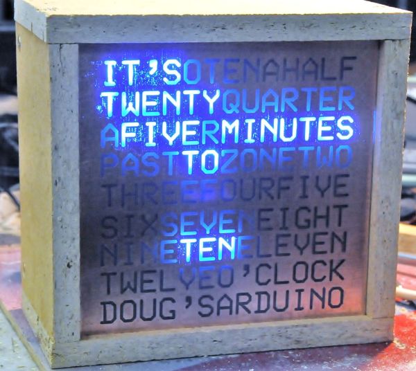
So, here it is – The word clock – constructed using an Arduino!
I am now able to sell all sorts of components, ranging from complete clocks, through to kits, through to individual modules and components. Please visit my web site www.dougswordclock.com for further information.
Step 1: The new hardware – Controller board schematic
BETTER DRIVERS
My original clock used discrete transistors to drive the array of LEDs. I have realised that while that approach works fine for a project that I have built for myself, it makes it more complex for others to build, so this new clock uses ULN2003A Driver ICs. The ULN2003A contains a set of darlington transistors in a convenient DIP package, so there is MUCH less soldering to do.
A NEW PCB
I have also re-designed the PCB to make construction much simpler – The Arduino controller simply plugs into the new PCB. If you want, once you have constructed the clock, you can recover your Arduino board by purchasing an ATMega168 with a boot loader, and populate the PCB with just the new Microcontroller and a crystal.
IS THIS JUST A NEW SHIELD?
In the spirit of Arduino development, it would be fair to say that the controller board was a 24 output LED (or relay) driver shield. It is just as happy to turn on a big set of 24, 12 volt relay coils as it is turning on a bank of LEDs.
Below you will find the new schematic diagram for the controller board as a PDF file.
Note that you should look at step 4 to understand what resistors to use. Don’t simply use 360R and 36R with supply voltages above 10v. You will need to use 680R and 270R instead.
 WordClock-Arduino-Schematic-V1.0.pdf(595×842) 64 KB
Step 2: The hardware – Make the controller board
If you want to etch your own board, you can download the attached a PDF file and follow the steps I used.
TONER TRANSFER IS EASY
When I made the board, I photocopied the page onto Toner Transfer paper (Press-n-Peel Blue), then I used an old laminator to transfer the image onto a piece of very clean PCB stock. I etched the board in a mixture of Hydrochloric Acid and Hydrogen Peroxide etchant. There is a brilliant Instructable that describes the process at www.instructables.com/id/Stop-using-Ferric-Chloride-etchant!–A-better-etc/
BE SAFE
When you etch ANYTHING – make sure you are wearing safety goggles, and old clothing.
CLEAN UP
When the etch process is complete, everything was rinsed very well under running water to remove all traces of etchant. Just before I rinsed everything, the etchant was collected for use with the next project.
DRILL HOLES
Once the board had been rinsed and dried, I used a Dremmel to drill the holes, and removed the Press-n-Peel film using some steel wool, detergent anf good old elbow grease.
This time, I took buckets of photos of the process – It is very pretty!
I personally really enjoy making printed circuit boards, and I am sure that you can make them yourself. However, if you would like your own controller PCB, I am able to supply blank, or pre-assembled boards. Have a look at the last step for further information.
WordClock-Arduino-PCB-V1.0.pdf(595×842) 37 KBStep 3: The hardware – Populate the controller board
Now that we have an etched, sized, drilled and cleaned PCB, we need to start mounting components.
POPULATE THE PARTS IN ORDER OF SIZE
I soldered all of the components, using the stencil layout as a reference. I started by mounting the six jumpers that I needed to place because I used a single sided board. Then I soldered the header pins and the IC sockets, Then the resistors, diodes and off board connectors. Finally, I plugged in the Integrated Circuits and the Arduino Board, and that step was done.
Note there there was a small change with the final board version – the two resistors (R2 and R3) are actually mounted below where the photos show them, and jumpers are installed in the corresponding space. Just follow the parts layout for the exact placement.
It was a very restful 30 minutes to do the soldering. Make sure that you use some sort of fume extraction when you solder. To many fumes can end up being bad for you.
Here are heaps of photos, showing the steps I used to populate the board.
LED’s
For more detail: The Word Clock Arduino version
- Why was the original clock redesigned?
The author redesigned it to use an Arduino because it is simpler to develop for, has a lower barrier to entry, and is self-programmable via USB. - What driver components are used in the new version?
The new clock uses ULN2003A Driver ICs which contain Darlington transistors to reduce the amount of soldering required. - Can the Arduino board be recovered after building the clock?
Yes, you can recover the Arduino by installing an ATMega168 with a boot loader and the necessary support components on the PCB. - What power supply options does this clock support?
The clock uses a 12 Volt DC supply and can run off a wall wart or D cell batteries. - How should resistor values be adjusted for voltages above 10v?
If the supply voltage is above 10v, you must use 680R and 270R resistors instead of 360R and 36R. - What method did the author use to make the PCB?
The author used toner transfer paper and a laminator to transfer the image onto PCB stock before etching. - Is the controller board compatible with relays?
Yes, the controller board acts as a 24 output shield that can turn on relay coils just as easily as LEDs.