Summary of Temperature and Servos
This tutorial demonstrates building an Arduino-based system that uses a temperature sensor to automatically adjust a servo motor, simulating window opening based on ambient heat. The project involves wiring components like a breadboard, LED, resistor, and sensor to the Arduino, then writing code to read temperature data and map it to specific servo angles.
Parts used in the Temperature-Controlled Servo Project:
- An Arduino
- A Breadboard Small
- A servo motor
- An LED
- A 150Ω resistor
- A temperature sensor
Two other tutorials I have written step you through the basics (Arduino 101) and how to create a really basic data logger (Arduino Datalogger – simple). This tutorial will step through how to attach servo motors, and use temperature sensor to move it!
The premise is that often, you want to respond to some input and make something happen. Most tutorials show you how to make lights come on or make a sound. Here, I want to show how you can use a simple servo motor to open something (like a window) in proportion to the ambient temperature.
Let’s get started!
Step 1: Adding the Components
For this tutorial, you’re going to need:
- An Arduino
- A Breadboard Small
- A servo motor
- An LED
- a resistor, set to 150Ω
- a temperature sensor
I use Tinkercad for all tutorials until I get into classes or complex libraries, so head over there and get an account! To add the components, you’ll need to open the Components draw and search/scroll, making sure you have selected “all” instead of “basic” in the components drop down selector.
If you’re not sure how to use these, or if at any time you get lost, go back to Step 1 and use the 101 and datalogger tutorial to get started. They are a good starting point.
Let’s wire these up.
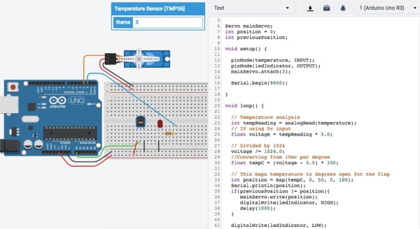
Step 2: Wiring Up
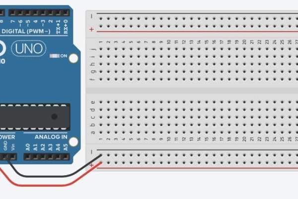
A reminder that all columns in a breadboard are connected, but there is a gap in the middle that disconnects the top array from the bottom.
- Use the first image as a guide on how to wire up the 5v and GND wires from the Arduino to the breadboard. Connect the 5V and GND ports on the Arduino to the breadboard. Essentially, these two power rails provide a greater number of ports to access power when prototyping.
- Connect the bottom of the board to the top. Make sure you match GND / Negative (black) to 5v / Positive (red).
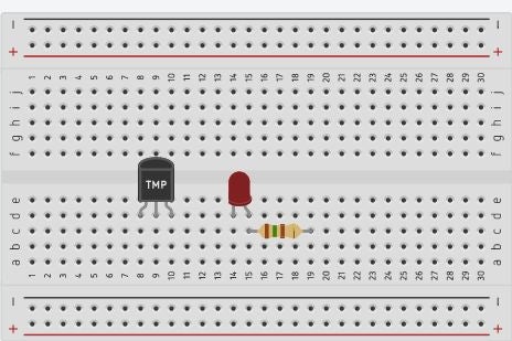
- Make sure all components are on the bottom half of the breadboard, except the servo, and that they are crossing the columns. This is important so we don’t cross any wires.
- Add the LED (image 2).
- Use the resistor and connect to one of the pins (I used the anode).
If you used the anode (and it is easier to follow the wiring diagram in the image), then connect the cathode (negative) to the GND line on the breadboard.
Quick tip! If you roll your mouse over the end of the pins on a component it’ll tell you which is the anode and cathode, or signal etc. - Connect the temperature sensor. Make sure the left leg goes to 5v. The right leg goes to GND. The middle leg must be connected to the A0 pin.
This is an analogue device and as such, needs an analogue pin. We could use digital and tell it to receive analogue, but we have enough pins. - For the servo, we have three wires. These include 5v, GND (ground) and a signal wire.
- Connect the brown wire on the servo to GND on the breadboard.
- Connect the red wire on the servo to a 5v pin on the breadboard.
- Connect the orange wire to digital pin 3 on the Arduino.
If you’re unsure, check the images above!
Step 3: The Code

In this example, I am assuming I have a house in a hot climate. I would like to open windows when it gets hot so I can maximise airflow, because I have a condenser air con that requires massive positive pressure in the house to cool the place down. So, we are going to automatically control the windows to maximise airflow.
Let’s get into the code nice and quickly!
#include <servo.h>
This is the first time (in this series) we have used a library. A library is like a box with a series of folders in it. In each folder are sheets of paper, and each one has special instructions on how to use specific devices. You can “include” these folders in your code, which makes it faster for you to write your code!
In the past, I have written plugins for webapps and other software which are distributed free. It’s a great way to give back to the community! Once you have developed a good skill base in code, it’s a worthwhile opportunity to engage in open source.
We use the #include instruction to tell Arduino that it will use the library. If it is a global library (something you installed with the package manager or built in to the Arduino, like math.h), then you will put it between the <> symbols.
Later, you’ll learn to write your own and if you store them in the project folder, you’ll put the filename between double quotes, “like this”. That’s because the compiler (the program that converts the code from something we can read to something the Arduino can read) needs to reference the file in the folder, not on the global scope.
The next block of code should look fairly familiar, so we’ll just look at the new features.
// Define constants
#define temperature A0
#define ledIndicator 2
#define servoPin 3

// Startup the servo class
Servo mainServo;
So, we have defined the two constants we’re going to use. These are the pins connected to sensors or outputs. We also defined the servo pin.
You can see the line Servo mainServo – this is where we instantiate the class Servo we installed with the library. This is like turning on the coffee machine to warm it up (I love coffee….). It’s ready to go! In this case, mainServo is the name we have given this new instantiation. This is important, because with classes, I could have 1, 2 or many servos running at the same time! This is why we use classes, because they are little packages on their own we can use many times and do many things with.
// Define variables
int position = 0;
int previousPosition;

void setup() {
	pinMode(temperature, INPUT);
	pinMode(ledIndicator, OUTPUT);

	// Tell mainServo which pin it is connected to
	mainServo.attach(servoPin);

	Serial.begin(9600);
}
This block of code above is fairly consistent with everything else we have done. The only major note to make is of the mainServo.attach() function call. Here, we have told mainServo to run a function called attach() and inside the round braces, indicated the pin we are attaching the servo to. This helps the servo know where to send the signals later.
If you’re wondering how we know what function calls to make inside our library, all libraries have documentation. This documentation tells you what functions exist inside the library, and how you can use them (for example, what parameters each function takes).
void loop() {
}
The next block of code goes within the loop() code.
// Temperature analysis
int tempReading = analogRead(temperature);
// If using 5v input
float voltage = tempReading * 5.0;
// Divided by 1024
voltage /= 1024.0;
//Converting from 10mv per degree
float tempC = (voltage - 0.5) * 100;

// This maps temperature to degrees open for the flap
int position = map(tempC, 10, 50, 0, 180);<br>
In this block, we are completing temperature analysis (we saw this in the data logger tutorial). Essentially, we’re taking the analog signal sent in by the temperature sensor and converting it into degrees.
The map() function allows us to convert this into something useable. Rather than perform complex maths that would take many lines, we convert it like this:
map(variableValue, fromLow, fromHigh, toLow, toHigh);
What this does is take the value of the variable we have (like degrees) and convert the minimum possible value and the maximum possible value in might give us (in this case, I set the minimum to 10degrees and the maximum to 50degrees. These are the minimum and maximum values I am expecting from the temp sensor, and I also know at 10degrees, I would like the windows completely closed to keep the warmth in! Whilst at 50degrees, I want them completely open for max air flow!
Source: Temperature and Servos
- What is the main purpose of this project?
The goal is to use a servo motor to open something like a window in proportion to the ambient temperature. - Which pin should the middle leg of the temperature sensor connect to?
The middle leg must be connected to the A0 pin because it is an analogue device. - How do you calculate the temperature in Celsius from the reading?
You subtract 0.5 from the voltage and multiply by 100 to convert from 10mv per degree. - What function maps the temperature value to the servo angle?
The map function converts the temperature range of 10 to 50 degrees into a servo position of 0 to 180. - At what temperature does the project set the window to be completely closed?
The window is set to be completely closed when the temperature is 10 degrees. - Which digital pin is used for the servo signal wire?
The orange signal wire from the servo connects to digital pin 3 on the Arduino. - Why is the servo.h library included in the code?
The library provides special instructions and functions needed to control the servo motor efficiently. - What happens if the temperature reaches 50 degrees?
The servo moves to position 180 to ensure the windows are completely open for maximum airflow.