Over the years, I have built several large robots using a custom-made robotics driver that I created called the SmartRover system. This driver was initially used for my SmartRover robot that I built which ran at a peak current of 60 amps at 24 volts. Obviously, the SmartRover can be overkill for many beginners. With the intentions of sharing the fundamentals of robotics with my club and with many members being interested to acquire hands-on skills with robots, I decided to design a DIY robot of a smaller scale. This ultimately became known as the SparkRover, an affordable robotics kit that I exclusively dedicated to sharing with the Purdue Mechatronics club.
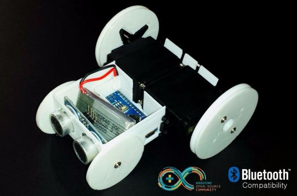
The SparkRover is an open-source 3D printed robotics kit that can be controlled by a Smartphone and can avoid walls. This robot can be controlled through Bluetooth and can be a great way for beginners to learn about the Arduino environment, serial communications, the workings of servo motors, and ultrasonic sensors. The robot is rechargeable and programmable, which is perfect for educational purposes.
The SparkRover can be used for applications including but not limited to:
- Robotics Learning Platform
- GoPro Automatic Camera Dolly
- Panorama Camera Assistant
- Maze Solving Robot
- Robot Racing
Disclaimer: Common knowledge and safety understandings of power tools and other equipment used should be exercised when operating such items that may cause injury or death. This project is provided “as is” for educational purposes. The author is not responsible for any accident or damage as a result of this project.
Step 1: Parts, Tools, and Files
If you are a hobbyist, you can find most of these parts in your toolbox or workshop. Otherwise, a quick trip to the hardware store will get you most of the parts.
We are offering this project as a kit for students at the Purdue Mechatronics club. If you would like to support our development and reduce the hassle of finding parts, please order a SparkRover kit for yourself (which contains all the parts to assemble the robot), by visiting our website: Order the SparkRover Kit
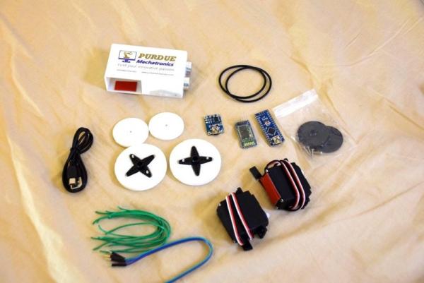
These are the parts you will need to assemble the SparkRover:
- 3D Printed Parts (1x – SparkRover Chasis, 1x – Cover for the Chasis, 2x – Front Wheel, 2x – Back Wheel)
- 2x of 55mm O-Rings
- 2x of Futaba S3003 Servo pack (contains a servo, servo horns, screws, etc.)
- HC05 Bluetooth module
- Arduino Nano v3
- 26 AWG stranded wire (or jumper wires)
- Push button latch switch
- Small 3.7v LiPo battery
- 3.7v to 5v Step-Up chip
- Ultrasonic sensor
If you have continuous-rotation servos, please use those instead of using Futaba S3003.
These are the tools you will need to assist you during assembly:
- A soldering iron and solder (optional)
- Needle-nose Pliers
- Nippers
- Scissors
- Wire strippers
- Phillips / Flathead screwdriver
- Mini USB cable
- Hot Glue gun (or double-sided tape)
- Blue tape
These are the resources we will be using throughout this Instructable:
- 3D Printed Parts (1x – SparkRover Chasis, 1x – Cover for the Chasis, 2x – Front Wheel, 2x – Back Wheel)
- Servo Stabilize – Arduino Code
- HC05 – Arduino AT commands
- SparkRover – Arduino Bluetooth Control
- SparkRover – Arduino Panorama Mode
- SparkRover – Arduino Wall Avoider
- SparkRover – Android App for Bluetooth Control (currently under development)
Step 2: Print the 3D Files
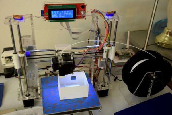
The SparkRover comprises of four 3D printed parts (STL files for each). Proceed to printing the following:
- 1x – SparkRover Chasis
- 1x – Cover for the Chasis
- 2x – Front Wheel
- 2x – Back Wheel
You can arrange these objects on the printbed of a MakerBot, Reprap, and most 3D printers. Sometimes, you may have to print the parts separately. Set infill to a minimum of 20% and try to print on 1.75mm PLA filament on standard quality. Be sure to enable supports.
Step 3: Preparing the Wheels
Take the two 3D printed back-wheels and place them flat on a table. Perform the following for each wheel:
- Take the cross-shaped servo horn and align it adjacent to the dip in the wheel.
- Take two (or four) silver screws and tighten them on the front side of the wheel so that the wheel is held to the horn. Do not over-tighten the screws.
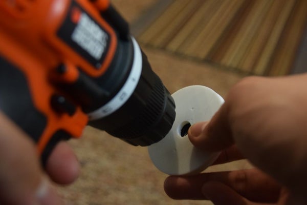
Take the two 3D printed front-wheels and secure them with a vise or pair of pliers. Perform the following for each wheel:
- Take a 3/32″ drill bit and drill through the center of the wheel. Ensure the hole is not threaded.
- Try placing a silver screw through the hole of the wheel and ensure there is minimal friction when rotating it.
- Gently tighten the screw with the wheel on the front side of the SparkRover chasis.
Step 4: Preparing the Servos
If you have continuous-rotation servos, please skip this step and use those instead of using Futaba S3003. The SparkRover kit contains two Futaba S3003 servos that need to be modified into continuous rotation servos.
This step is intended to teach you how to turn a regular servo into a continuous rotation servo. Knowing this can give you a better understanding of how a servo works and can open your mind to more ideas in the future.
It is important to perform this step gently and carefully. You can possibly damage a servo permanently if you are careless while opening or modifying a servo. Furthermore, this tutorial is intended for the Futaba S3003 servos. Other servos may have structures that can vary.
Perform these procedures on each servo. Be patient, it make take up to 45 minutes on your first try.
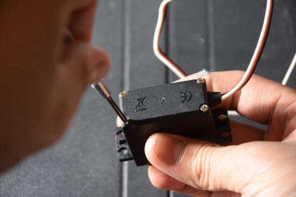
Removing Mechanical Stop (top portion)
- Firmly place a piece of blue tape on each side of the lower crease of the servo.
- Take a Phillips head screwdriver and unscrew the four screws on the bottom of the servo.
- Gently remove the top cover of the servo while holding it in upright position.
- Remove the middle gear. Remove the metal bearing.
- Take the nippers and carefully cut off the mechanical stop from the last gear.
- Replace the middle gear and metal bearing.
- Replace the top cover of the servo while aligning the middle gear in the middle.
Removing the Motor and Circuits (bottom portion)
- Remove the blue tape. Place it on the upper crease of the servo.
- Remove the bottom cover of the servo gently. Pull the motor in an outward direction.
- Gently lift the circuit board upward. You should see a potentiometer attached to the enclosure.
- Use pliers to bend the plastic latches holding the potentiometer until they become loose.
- Push back the plastic latches and sharply pull the potentiometer from the enclosure.
- Take the nippers and cut off the top shaft of the potentiometer.
Calibrating the Potentiometer
- At this point, you should have the “guts” of the servo. Connect the servo’s white wire to pin 9 on Arduino.
- Upload the “Servo Stabilize” code to your Arduino. Hook up the servo’s GND and VCC to the Arduino.
- Observe the servo motor closely. If the shaft is moving, keep adjusting the potentiometer until the motor stops moving completely.
- Once the motor stops moving, put a drop of hot glue on the potentiometer to hold it in place. You may also use blue tape instead.
- Carefully put the motor back inside the servo enclosure. Reassemble the servo and tighten the screws. During this step, keep the Arduino program running until you completely finish reassembling the servo. At any point, if the servo start jittering again, open up the servo and re-adjust the potentiometer.
Once you have re-assembled the servo, it should now be able to have unlimited rotation.
Step 5: Mounting the Drive System
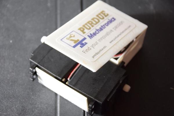
- Hot glue (or use double-sided tape) to adhere the back of both servos together with the shafts facing opposite direction. Place the finished back wheels on both servo shafts and tighten with a black screw.
- Hot glue (or use double-sided tape) to adhere the servos to the back of the chassis.
- The servo wires should protrude from the back of the chassis. Route these wires underneath the chassis and insert them through the hole to the front of the chassis. Secure the wires with blue tape or hot glue.
- Connect the servo wires to the Arduino by either cutting, stripping, and soldering them OR by using male jumper cables to make the connections.
The wiring for the servos are as follows:
Left Servo (white): Digital pin 9
Left Servo (red): 5v
Left Servo (black): GND
Right Servo (white): Digital pin 10
Right Servo (red): 5v
Right Servo (black): GND
Step 6: Using the Bluetooth Module
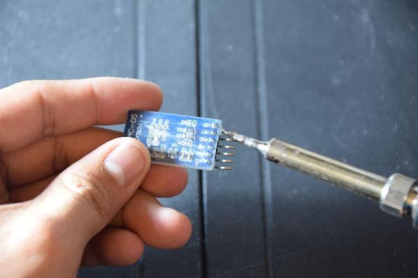
Before you actually use the HC05 Bluetooth module, you should customize it first. Follow these steps to set up your HC05 Bluetooth module for the SparkRover:
Wire the HC05 with the Arduino
- HC-05 GND — Arduino GND Pin
- HC-05 VCC (5V) — Arduino 5V
- HC-05 TX — Arduino Pin 10 (soft RX)
- HC-05 RX — Arduino Pin11 (soft TX)
- HC-05 Key (PIN 34) — Arduino Pin 9
Upload the “HC05 – Arduino AT commands” to your Arduino (code shown below)
//Purdue Mechatronics Club (Spring 2016)
//SparkRoverV2 Wall Avoider
#include <SoftwareSerial.h>
SoftwareSerial BTSerial(10, 11); // RX | TX
void setup() {
pinMode(9, OUTPUT); // this pin will pull the HC-05 pin 34 (key pin) HIGH to switch module to AT mode
digitalWrite(9, HIGH);
Serial.begin(9600);
Serial.println(“Enter AT commands:”);
BTSerial.begin(38400); // HC-05 default speed in AT command more
}
void loop() {
// Keep reading from HC-05 and send to Arduino Serial Monitor
if (BTSerial.available())
Serial.write(BTSerial.read()); // Keep reading from Arduino Serial Monitor and send to HC-05
if (Serial.available())
BTSerial.write(Serial.read());
}
Open the Serial Monitor in Arduino, and type the following commands(line by line):
AT+NAME=SparkRover
AT+PSWD=2468 (or whatever you want)
Update your wiring
- HC-05 GND — Arduino GND Pin
- HC-05 VCC (5V) — Arduino 5V
- HC-05 TX — Arduino RX0
- HC-05 RX — Arduino TX1
- HC-05 Key (PIN 34) — nothing
Read more: SparkRover – 3D Printed Smartphone Controlled Robot