This instructable was created in fulfillment of the project requirement of the Make course at the University of South Florida (www.makecourse.com).
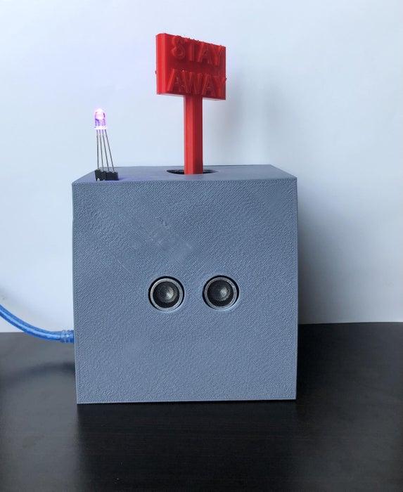
The Social Distancing Robot is a robot concerned with its health in the midst of the current pandemic. It has an RGB LED to indicate how close you are to it. If you are far from it, the green LED will be on, if you get close, the purple LED will be on and if you get too close, the red LED will be on, the robot will make a loud noise, and spin the flag with the “stay away” message.
The robot is able to measure your distance from it thanks to an ultrasonic sensor at the front. So remember, keep your 6 feet distance and avoid making the Social Distancing Robot mad!
Step 1: Parts Needed
Here is all you are going to need to do this project.
MATERIALS
- Arduino Uno R3
- Breadboard
- Jumper wires
- Ultrasonic sensor (distance sensor)
- Passive or active buzzer (I used a passive buzzer)
- Stepper motor
- Stepper motor driver
- RGB LED
- 3×110-ohm resistors
EQUIPMENT
- CAD software (I used Autodesk Fusion 360)
- Slicer software (I used Flashprint)
- 3D printer
- Screws
- Screwdriver
Step 2: CAD Model
One thing that I learned is that the more time you put into your CAD model the less frustrated you will be with your 3D prints. So think carefully about all the screws, holes, and wiring that you will need. Also, you do not need to stress yourself out too much about having the perfect model at first. Think of your first model as a prototype. Just make sure you are paying enough attention to details.
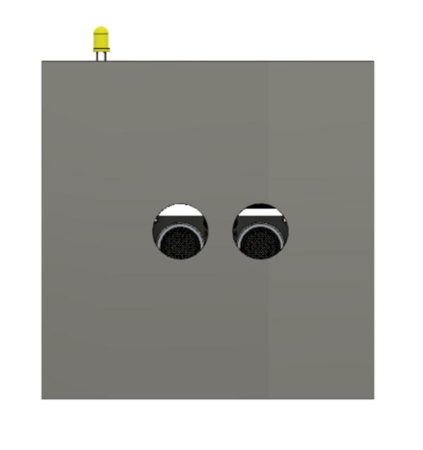
For the Social Distancing Robot, you will only need 4 components. The main box, the stay-away flag, the back wall, and the shaft base that will connect the stepper motor and the flag. I have added an STL file with my CAD design. You can use it and modify it to your preference.
After you have your CAD design ready, export it as an STL file and use a slicer (I used FLashprint) to 3D print your design.
Step 3: Circuit Design
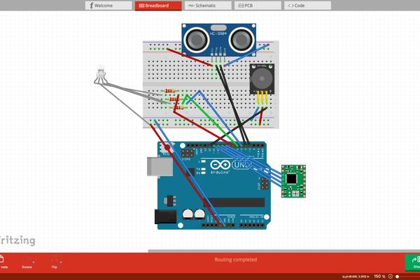
Here is how I set up my circuit. The green rectangle is the stepper motor driver. The software I used did not have the driver I used for my project which was the ULN 2003 Stepper Motor Driver Module. I connected the pins 1N1,1N2,1N3,1N4 on the driver to the pins 8,9,10,11 on the Arduino in this order.
To power the Arduino, I connected it to my computer with a USB cable, but you can also use a battery.
Step 4: Arduino Code
The Arduino code for this project is fairly simple. I commented on the lines so you can have a better understanding of the code. The only function you will need to know is the if-else conditional.
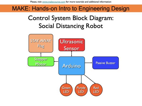
The Arduino will control all the electronic components and the ultrasonic sensor will serve as an input for the Arduino, which will trigger several functions on the Social Distancing Robot.
Step 5: Assembly
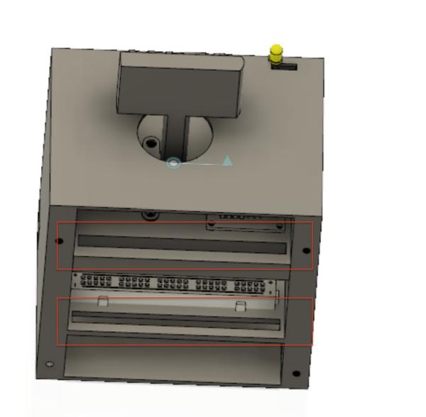
Before assembling, make sure to place all the wires in the rectangular holes I circled in red.
1. Start connecting the LED on the breadboard with resistors then connect the resistors to the Arduino
2. Place the ultrasonic sensor and the passive buzzer on the breadboard and then connect them to the Arduino
3.For last, screw the stepper motor and the stepper motor driver and connect them to the Arduino
Source: Social Distancing Robot