Summary of SmartMesh – Arduino and Android Controlled Pneumatic Facade
This project, SmartMesh, is an Arduino-controlled pneumatic facade element developed for Multimodal Media Madness 2014 at RWTH Aachen. Each element uses two air-filled latex balloons driven by pumps and valves, controlled by temperature and light sensors to regulate ventilation, light and thermal comfort. Elements close during bad weather and can be grouped for aesthetic facades. The build uses CNC/laser-cut chassis and a custom PCB with MOSFETs to drive pumps and valves. Documentation includes CAD and Eagle files and describes construction, electronics, and assembly steps.
Parts used in the SmartMesh:
- Arduino Uno (StarterKit+ for Arduino)
- 4x magnetic valves (Pollin)
- 2x 12V vacuum pumps (ROB-10398)
- SeeedStudio Bluetooth Shield
- 6x MOSFET IRLZ24N
- 6x Diode 1N4007
- 6x 10K Ohm resistors 1/4W
- 2x LM35CZ temperature sensors
- 1x TSL2561 light sensor
- TDK Lambda LS100-12 power supply
- 6x 220 Ohm resistors
- 1x DC connector
- 2x digital taster (push buttons)
- Extra strong latex balloons Ø 55 cm or more
- Thin brass pipe (2.0–2.5 mm)
- Copper plate for PCB
- Wires
- Solder
- Drill
- MDF panels and weather-resistant outer material for chassis and mesh
This project was part of Multimodal Media Madness 2014, hosted by the chair for Computer Aided Architectural Design (CAAD) and the Media Computing Group of RWTH Aachen University. For more Smart Skins, please check this page: http://hci.rwth-aachen.de/m3_ss14
During this project, the students were asked to develop smart, intelligent facade elements under the general topic “Home Automation” which should then be used as addable elements for small houses (study rooms) which are constructed after the open source concept of the WikiHouse (see WikiHouse for more information).
Our group got the idea to create the “SmartMesh” which is basically an arduino controlled facade element that contains two balloons which can be filled with air and evacuated using small handy pumps in coordination to the inputs of two temperature sensors (one outside and one inside the house), as well as a light sensor.
PURPOSE
The SmartMesh reacts to the outside and inside environment and ensures a pleasant indoor climate – thermal comfort. It controls the light and heat transfer between the inside and outside and also provides the inside with fresh air. The smart facade senses bad weather and closes in order to prevent for example inside water damages. The grouping of more smart elements provides an aesthetic architectural value trough the fragmented surface.
Note: We are going to update the Instructable from time to time in the following days.
by Hasan Ayhan, Tobias Welschenbach, Snezhina Shukina
Step 1: Component List & Project Cost
The main components (electronical parts only, for the constructing materials refer to step 3 of this Instructable) are as follows:
- A StarterKit+ for Arduino containing an Arduino Uno microcontroller and several parts to begin with. Watterott 35,50 EUR (Any Arduino Uno will do, however you might have to buy some parts which were already contained in this set, seperately)
- 4x magnetic valves Pollin 2,50 EUR each
- 2x 12V ROB-10398 Vacuum Pump Sparkfun (around 15 EUR each from German Sparkfun retailers)
- SeeedStudio Bluetooth Shield Watterott 21,80 EUR (other BT Shields or BT modules might also work but there has to be some changes done in the code)
- 6x MOSFET IRLZ24N (We had to use one from the StarterKit because one of the others turned out to be defective but the ones from the StarterKit should also suffice for our project.)
- 6x Diode 1N4007 (5 pcs are included in each kit, we had two of them)
- 6x 10K Ohm resistor 1/4W , 10 pcs included in the kit so enough of them 🙂
- 2x LM35CZ temperature sensor Watterott 3,00 EUR each
- 1x TSL2561 light sensor Watterott 7,74 EUR
- 1x TDK Lambda LS100-12 power supply Conrad 25,11 EUR
- 6x 220 Ohm resistor (included in the kit)
- 1x DC Connector Conrad 1,79 EUR
- 2x Digital Taster (any taster should do, as long as not too much force is needed to activate it, because the balloon has to activate it)
Additionally, the project used the following smaller components and accessories:
- A copper plate for making the printed circuit board
- wires
The following tools were used:
- Solder
- Drill
Step 2: Constructing the facade element chassis
COMPONENTS (ARCHITECTURE)
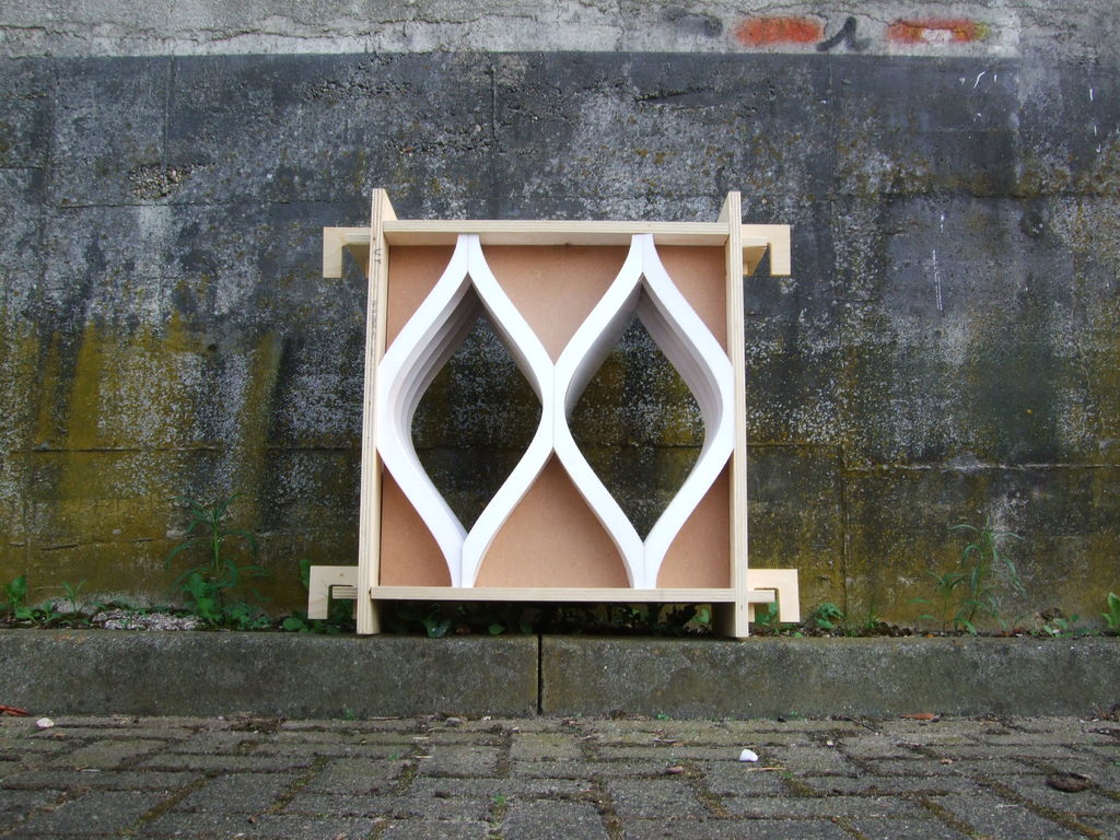
1. An optional (wooden) frame with the dimensions 562 x 562 x 281 mm, which makes it easier to build the panel and also a way of grouping the elements for the development of larger facades. In my opinion a grouping without the frame looks better.
2. An inner chassis, that gives the form of the mesh and also serves its purpose of integrating the electronics and vacuum pumps for each pneumatic fragment.
3. A group of two fragments, which gives the structure. Each one is filled with one latex balloon.
4. An extra strong latex balloon Ø 55cm or more – the longer the form is the better. It has to fill in the inner form of the mesh structure. In order to fix the balloon you will need a thin brass pipe (2.0-2.5mm) for each balloon.
5. Because of the outside conditions like rain the mesh needs a small pitch but only on the upper side, so that water flows down and not gets inside the mesh and provides any damage.
MACHINES USED
For building of one facade element a CNC milling machine and a Laser Cutter are used. The inner chassis is cut from a MDF panel by the CNC milling machine, but the inside of the chassis is hollow with enough space for all the electronics that you want to integrate. It is important that the material exposed to the outside environment is water and weather resistant. For our model we used MDF panels. In this case a weather resistant coating is needed from the outside and a nice looking wooden coating from the inside. The mesh structure (3) is made by 2D “stripes” (in the form of the mesh) arrayed with a distance between each other from around 50 mm. This structure gives more space inside the inner chassis, is lighter but still stable and allows an easy revision and maintenance of the panels’ intergrated stuff.
MATERIALS
inside wood – MDF panel and a coating by choice (f.e. a wooden one)
outside aluminium – wood or wood with a coating is optional – in any case water resistant
HOW TO BUILD THE ELEMENT
Step I: get all the stuff you need
You are going to use the frame in order to build the element. The inner chassis is cut by the CNC machine. The mesh structure is cut by the laser cutter. For the chassis you need a MDF plane about 1000 x 700 mm (the square parts you do not need to cut with the CNC, but you might). For the mesh structure you need 3x planes of a water and weather resistant material 1mm thick. Here you will also find attached the 2D files for both machines. You also need glue for all the materials you have and a standard cutter.
Step II: building the chassis
Once you have cut all parts start building the element into the frame from the outside to the inside. First connect/glue the chassis parts – the MDF ones cut by the CNC machine. When you have done this, you are going to have the 6 parts (4 corners and the 2 middle parts), where you want to integrate the electronic stuff later. If you want to take off the frame later, you should not glue the 6 parts permanently to the frame but fix them by using just a little glue. Now you have the frame and the chassis build, but you still have the big holes in the middle, where you will put the mesh structure.
Step III: building the mesh structure
The mesh structure is cut in stripes, so you are going to array the mesh
stripes and connect the parts by coating them from the outside. You may have noticed that the stripes in the cut-file are separated in I (inside) and A (outside) stripes. First you need to glue the inner stripes, but be careful! you might want to put your electronics first. So first the inner stripes and the outside mesh structure (see cut-file 1 and 2) and then you can put the outside stripes, which gives the final form of the two fragments. From this point what has to be done is connect all the electronics and close the two fragments by coating them (see cut-file 3). For an instruction of how to connect the electronics refer to step 5 of this Instructable.
Step IV: connecting the balloon
Connect the ballon with the vacuum pump by fixing it to the top. (Additionally you can also fix the balloon to the bottom of each fragment, too, but we only connected the balloon to the hosepipe that comes from the pumps and then fixed the hosepipe to the top.)
We did not test this but fixing it also to the bottom of each fragment might provide a greater outer view because the balloon no longer just hangs down on the loosen side (bottom). So if you do this, you might also fix it to the side with the detailed space for it. In order to do this you put the thin brass pipe into the balloon. The pipe has to take the form of the meshes curve and to be fixed again. This enhances the look because the balloon will be filled with air starting from the fixed side developing to the other side.
Step V: getting rid of the annoying frame (additional)
Finally you can take of the frame by loosing it with a cutter – just cut between frame and element and it should loosen up, so that you can take out the element from the frame. (we did not do this either, again consider as additional)
Step VI: closing the element (consider this last step as additional also, for our project we did not do this, yet it might provide a better experience for under real-life conditions)
Close the two fragments from both sides, where the frame has been earlier. You will notice that you can still get to the electronics through the sides now when the frame is gone. This is going to be helpful for connecting more than one element in both directions – makes grouping possible not only visually but by wires.
Notes: The materials for the outer side of the panel (chassis and mesh structure) have to be water proved and weather resistant. A such coating can be used. The joints between chassis and mesh structure have to be absolutely waterproved especially to the outside environment.
 Fräsdatei.dwg278 KBLaserdatei 2.dwg301 KBLaserdatei 1.dwg298 KB
Laserdatei 3.dwg291 KB
Step 3: Constructing and Soldering the Printed Circuit Board (PCB)
Construction:
- a small introduction:
This was the first slightly complex thing we had to do because we had never done something like that before and few to none experience with electrical circuits and the electronic stuff 🙂
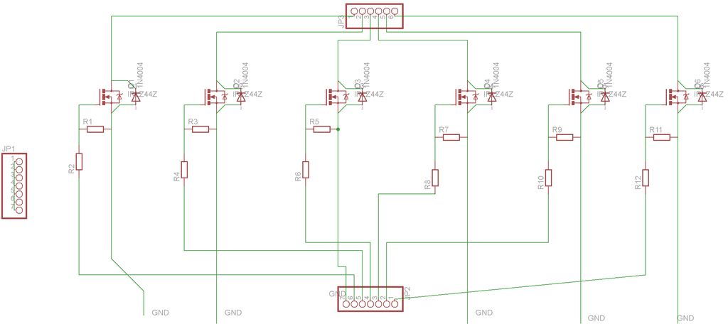
After figuring out how everything had to be connected, we began to create an early version of an Eagle shematic. For those who don’t know, Eagle is a free software which let’s you create shematics of electronic circuits to be then printed on a board. After a few improvements the following eagle shematic was created (maybe it’s not the most elegant shematic you might find but hey, it does work 🙂 Below you can also download the eagle file for creating the exact same board.
- a few words to the logics of the circuit:
Basically there are 6 MOSFETs in parallel each placed like for example in this great tutorial http://bildr.org/2012/03/rfp30n06le-arduino/http://bildr.org/2012/03/rfp30n06le-arduino/ with the exception that we placed the diodes in parallel not to the pumps or valves but to Drain and Source of the MOSFETs, which also works. We also added to each of the MOSFETs a 220 Ohm resistor in between the Gate and the Arduino’s digital pins, in order to not let high voltage damage the Arduino. For more details and reasons why there have to be diodes on each MOSFET as well as what a MOSFET is, I suggest reading some tutorials. The above mentioned is a good starting point and should suffice for our purposes.
So now came the part which might not be redoable for everyone (in fact only for a small part of people). We have the advantage in our university of having a PCB milling machine which does all the milling and creating of the board automatically once given the eagle file of the board. If you are interested in how this works you can watch the attached video, where we filmed the machine’s cutting of our board 🙂
Why even bother with creating such a PCB you might ask yourself? Well, firstly, the breadboard which came with our StarterKit does not allow current above 1A. Since our Pumps and Valves are in parallel the used current sums up so we had more than 1A definitely of current flowing and thus it was convenient to use an extra board for this whole project. Also we did not want to have several parts like MOSFETs etc. flowing around just connected by wires.
Soldering:
We assume for this step, that you know how to solder (if not we suggest you to first watch some tutorials for learning it) and just give you an explanation on what has to be soldered to which pin on the board. You have to solder 2x 7 pin connectors (in the picture the above ones), 1x 7 pin connectors (in the picture the bottom). Also you have to solder all the components (resistors, MOSFETs, diodes) exactly as in the picture with the notations and then you should be finished with the board. The other picture shows the other side of the board.
 MosfetPlatine.zip284 KB
- What does the SmartMesh control?
The SmartMesh controls light and heat transfer, provides fresh air, and closes during bad weather to protect the interior. - How are the balloons actuated in the SmartMesh?
The balloons are filled and evacuated using two 12V vacuum pumps and magnetic valves controlled by the Arduino. - Which sensors are used to drive the SmartMesh behavior?
The project uses two LM35CZ temperature sensors (inside and outside) and a TSL2561 light sensor. - What electronic driver components are used to power pumps and valves?
Six MOSFETs (IRLZ24N) with diodes 1N4007 and gate resistors are used to drive the pumps and valves from the Arduino. - Why was a custom PCB created for the SmartMesh?
A custom PCB was used because the breadboard could not handle the summed current above 1 A from pumps and valves, and to organize components like MOSFETs neatly. - What manufacturing methods are used to build the chassis and mesh?
The inner chassis is CNC milled from MDF and the mesh structure is laser cut from weather-resistant material. - How are balloons attached inside the mesh fragments?
Balloons are connected to hose pipes from the pumps and fixed at the top; a thin brass pipe can be inserted into the balloon to fix it to the mesh curve. - What power supply is specified for the SmartMesh electronics?
The project lists a TDK Lambda LS100-12 power supply. - Can the SmartMesh elements be grouped into larger facades?
Yes, elements are designed to be grouped visually and electrically to form larger fragmented facades.