
Summary of Sending and Receiving String via UDP using Arduino
This article demonstrates how to use an Arduino with an Ethernet Shield to send and receive text strings via the UDP protocol. It explains the circuit connections, including SPI pins and SD card control, and notes that network settings must be adjusted for the specific environment. A Processing sketch is provided for testing communication between the Arduino and a computer.
Parts used in the Sending and Receiving String via UDP using Arduino:
- Arduino Ethernet Shield
- Shield-compatible Arduino board
In this example, you will use your Ethernet Shield and your Arduino to send and receive text strings via the UDP protocol (Universal Datagram Packet). You’ll need another device to send to and from. The Processing sketch included at the end of the code will send to and receive from your Arduino running this example.
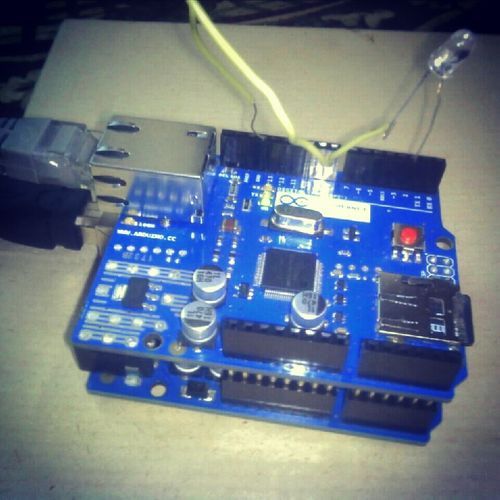
Circuit
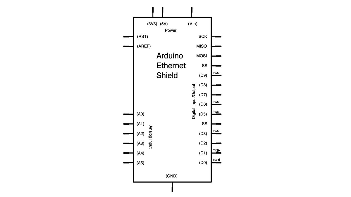
The Ethernet shield allows you to connect a WizNet Ethernet controller to the Arduino via the SPI bus. It uses pins 10, 11, 12, and 13 for the SPI connection to the WizNet. Later models of the Ethernet shield also have an SD Card on board. Digital pin 4 is used to control the slave select pin on the SD card.
The shield should be connected to a network with an ethernet cable. You will need to change the network settings in the program to correspond to your network.
image developed using Fritzing. For more circuit examples, see the Fritzing project page
In the above image, your Arduino would be stacked below the Ethernet shield.
Schematic
Code
/*
UDPSendReceive.pde:
This sketch receives UDP message strings, prints them to the serial port
and sends an "acknowledge" string back to the sender

A Processing sketch is included at the end of file that can be used to send
and received messages for testing with a computer.

created 21 Aug 2010
by Michael Margolis

This code is in the public domain.
*/
Hardware Required
- Arduino Ethernet Shield
- Shield-compatible Arduino board
For more detail: Sending and Receiving String via UDP using Arduino
- How does the Ethernet shield connect to the Arduino?
The shield connects to the Arduino via the SPI bus using pins 10, 11, 12, and 13. - What pins are used for the SD card slave select?
Digital pin 4 is used to control the slave select pin on the SD card for later models of the Ethernet shield. - Can this project work without another device?
No, you will need another device, such as a computer running the included Processing sketch, to send to and from your Arduino. - Does the code require network configuration changes?
Yes, you must change the network settings in the program to correspond to your specific network. - What protocol is used for sending and receiving data?
The project uses the Universal Datagram Packet (UDP) protocol. - What happens when the Arduino receives a message?
The sketch receives UDP message strings, prints them to the serial port, and sends an acknowledge string back to the sender. - Is there software included for testing the connection?
Yes, a Processing sketch is included at the end of the file for testing with a computer. - Who created this code?
The code was created by Michael Margolis on August 21, 2010.
