Summary of Project Idea: Morse Code Decoder with Interactive Input Options
Summary: I built a Morse code decoder using an Arduino Uno, LED, push button, and photoresistor. The button drives the LED; the photoresistor reads light to detect dots and dashes by measuring how long light stays above a threshold. I debugged circuitry (using a pull-down resistor) and code (using analogRead, millis, and state loops), added a pressbutton function for testing, and tuned thresholds/timings. Challenges included wiring, overheating Arduino, and adapting example code. Planned improvements include word/letter spacing and numeric decoding.
Parts used in the Morse code decoder:
- Arduino Uno
- Push button
- LED
- Photoresistor (light sensor)
- 10k ohm resistor (pull-down and photoresistor voltage divider)
- 330 ohm resistor (LED current limiting)
- Jumper wires
- Breadboard
- USB cable (Arduino to laptop)
Arduino
My goal for this assignment is to create a Morse code decoder, which can prove highly beneficial for socially distant interactions with friends. The decoder will offer two input options for Morse code: (1) manual clicking of a button to illuminate the LED light, and (2) detecting flashes from an external source, such as a Morse Code app on a phone. This will enable users to practice their Morse code skills and translate Morse code without having to learn it explicitly.
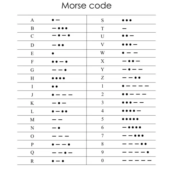
To accomplish this, I will require an LED, a button, and a photoresistor (light sensor). The button’s purpose is to activate the LED, while the photoresistor will detect when the LED is turned on. By analyzing the duration of the LED’s illumination, I can interpret it as a dot or a dash, which together form Morse code representing letters or numbers. As a beginner with the Arduino kit, I lacked confidence in coding the components and creating a suitable circuit. Consequently, I sought guidance from the Arduino website to understand how to utilize the button and the photoresistor effectively. The website provided step-by-step instructions for assembling the circuit with each component and furnished the corresponding code for circuit testing. By combining the insights from both sources, I successfully devised the circuit for my Morse code decoder.
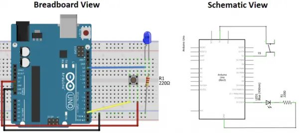
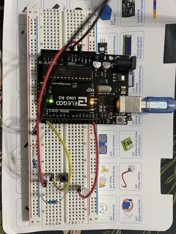
Step 1: Constructing the Circuit for the Button and LED.
The components required for this project include an Arduino Uno, a push button, an LED, resistors, jumper wires, and a breadboard.
The website discussed the LED’s unpredictable behavior when the button is not pressed, as the circuit behaves as an open circuit in that state. Specifically, the pin to which the button is connected becomes a floating pin, resulting in a sequence of random 1s and 0s being generated.
To address this issue, they introduced an external pull-down or pull-up resistor. This addition ensures that when the button is not pressed, a low or high state is achieved, respectively.
I opted for the pull-down approach. When the button is pressed, it will be in a HIGH state because the current flows from the 3.3V pin of the Arduino to pin 2 of the Arduino through the button. However, when the button is not pressed, it will be in a LOW state because pin 2 will be connected to the ground through the 10k resistor.
- To set up the circuit, link the 3.3V (instead of 5V to accommodate the photoresistor) from the Arduino to one end of the button. Connect the other side of the button to Pin 2 on the Arduino and connect it to the ground through a 10k ohm resistor.
- Establish a connection from Pin 13 of the Arduino to the anode of the LED (longer leg), and then connect the cathode of the LED (shorter leg) to the ground (GND) through a 330 ohm resistor (the resistor’s value determines the brightness of the LED).
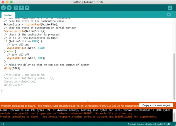
- Download the code and open it in the Arduino software. The code is designed to turn on the LED when the button state is high, and vice versa. To account for the rapid changes in the button state, a delay is incorporated, ensuring that the button’s output effect can be observed effectively.
- Establish a connection between the Arduino Uno and the laptop using the USB cable. Then, upload the code to the Arduino Uno in order to run the program.
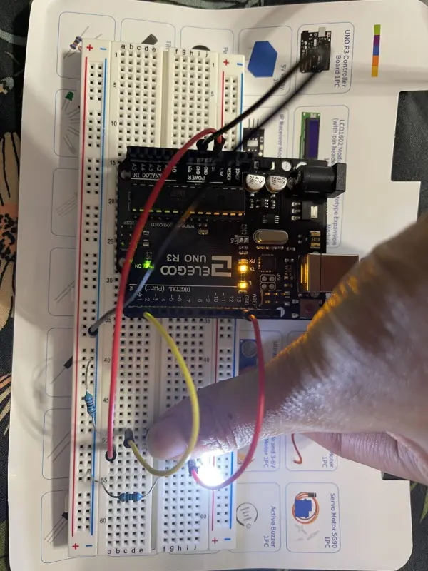
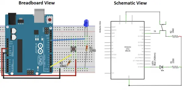
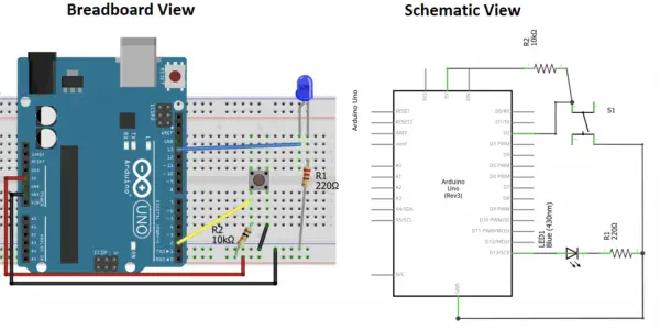
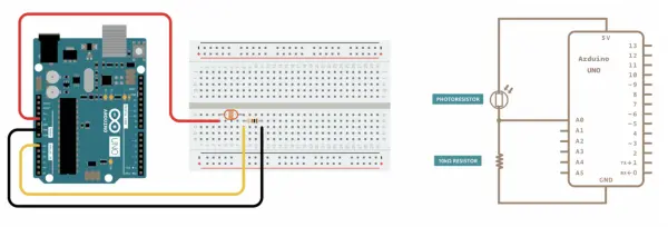
Step 2: Integrating the Photoresistor into the Circuit
The photoresistor’s resistivity varies based on the amount of light it receives, with lower resistance for higher light intensity. It consists of cadmium sulfide tape, which acts as a semiconductor. When photons strike the tape, electrons can pass through the semiconductor, resulting in decreased resistance.
On the website, they discussed how to measure the analog value using the photoresistor by utilizing the analogRead() function. This function converts the input voltage range of 0 to 5 volts into a digital value ranging from 0 to 1023 through the microcontroller’s analog-to-digital converter (ADC) circuit. The formula used to calculate the measured voltage (Vout) is Vout = Vin * (R2 / (R1 + R2)), where Vin is 5V, R2 is 10k ohm, and R1 represents the photoresistor value. In darkness, R1 ranges from 1M ohm, in daylight (10 lumen) it is 10k ohm, and in bright light or sunlight (>100 lumen) it is less than 1k ohm. Consequently, when the LED is activated, Vout will increase.
- Link one side of the photoresistor to the 5V pin on the Arduino Uno, and connect the other side of the photoresistor to both a 10k ohms resistor and an analog pin A0.
- Join the remaining side of the 10k ohms resistor to the ground (GND).
Initially, I faced some confusion while attempting to integrate the photoresistor circuit with my button/LED circuit. The process involved changing the pin connections for each wire, and I struggled to identify which wire belonged to which circuit. After three attempts at reconstructing the circuit, I eventually managed to get it right.
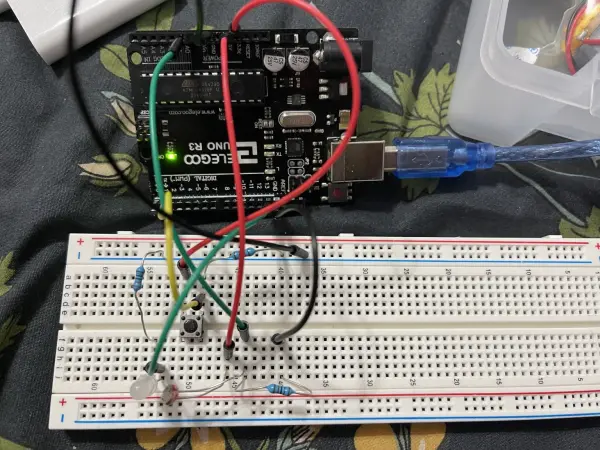
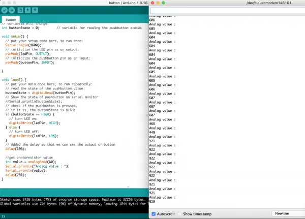
Through experimentation, I discovered that under normal conditions with room light, the analog value was approximately 600. However, when I turned on the LED, the analog value increased to around 900. Therefore, I set 700 as the threshold point to determine whether the LED is on or off. By measuring the duration that the analog value stays above 700, I can differentiate between a dot and a dash in Morse code.
Step 3: Implementing the Morse Code Translator in Code
As this is my first experience coding with Arduino, I was uncertain about the language’s syntax. To gain a better understanding, I reviewed a website that used Arduino to create a Morse code translator. The provided code took input directly from the button state (without the LED or photoresistor). Feeling a bit apprehensive about writing code, I attempted to modify the code to accept input from the photoresistor. However, after spending hours debugging, I couldn’t get the code to function properly with my circuit.
- In my attempt to adapt the code, I modified all the variables to correspond to the input from the photoresistor (analog value) within the void loop. However, when I executed the code, the analog value stopped displaying as the code got stuck in the while loop, with the analog value consistently below 700 amps. The issue arose because I couldn’t turn on the LED, as the code for activating the LED with the button was placed before the while loop.
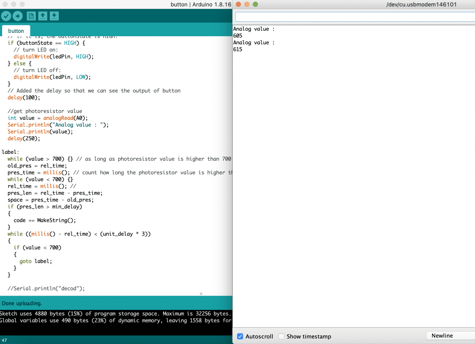
2. To address the button/LED issue, I first focused on understanding the code flow responsible for measuring the duration the light remains on. Instead of the LED, I used the flashlight function from my phone to illuminate the photoresistor and verify the functionality of the code. To gain insights into the code flow, I added print statements for ‘here’ statements, analog values, and pres_time (time the light remains on). Building upon the previous code, I decided to use the analogRead function directly, avoiding the need to store the value in a variable before its usage. This change enabled the while loop to access the most up-to-date analog value. As a result, the code is no longer stuck in the while loop, and the analog value is continuously updated whenever there’s a change in light intensity.
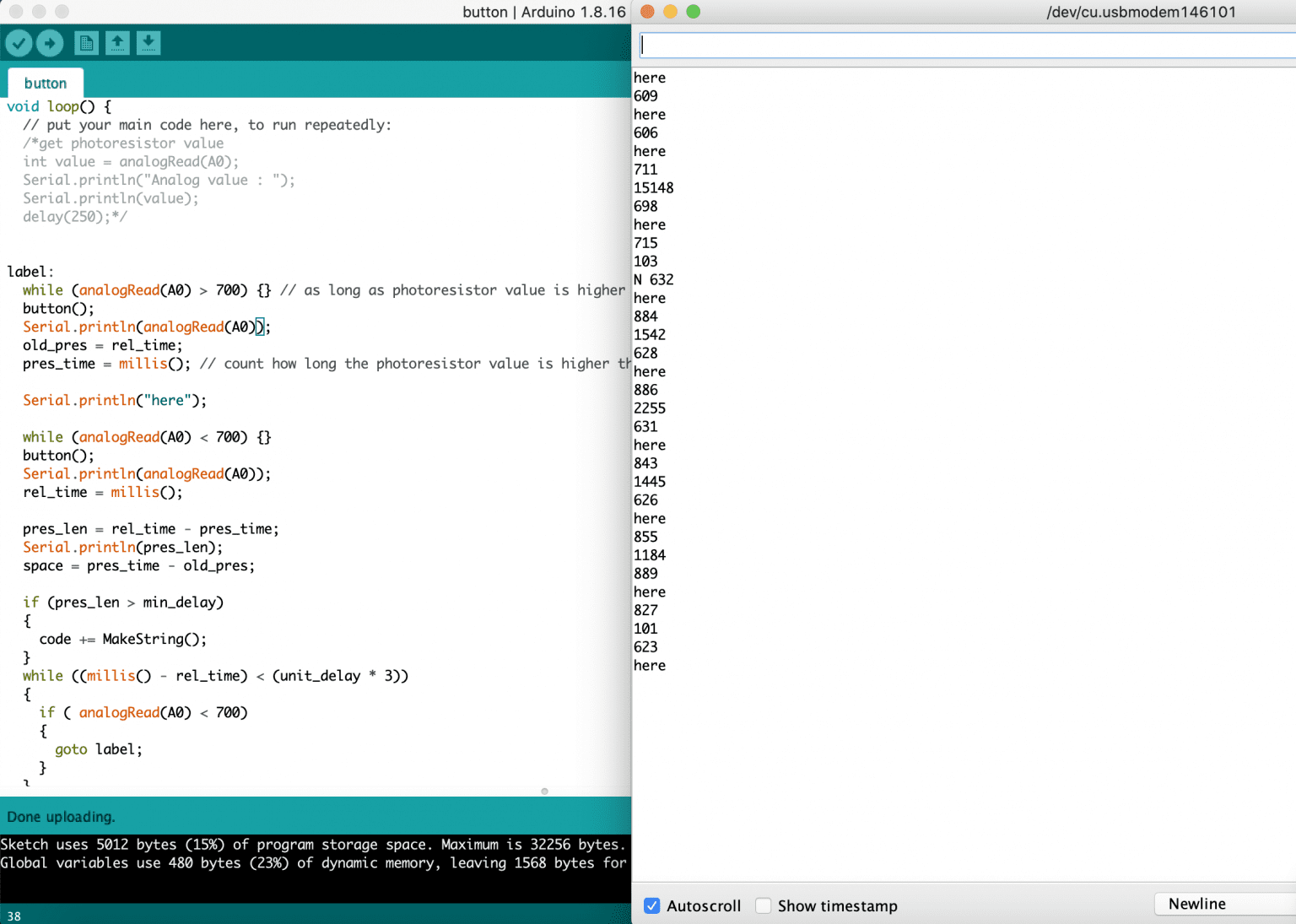
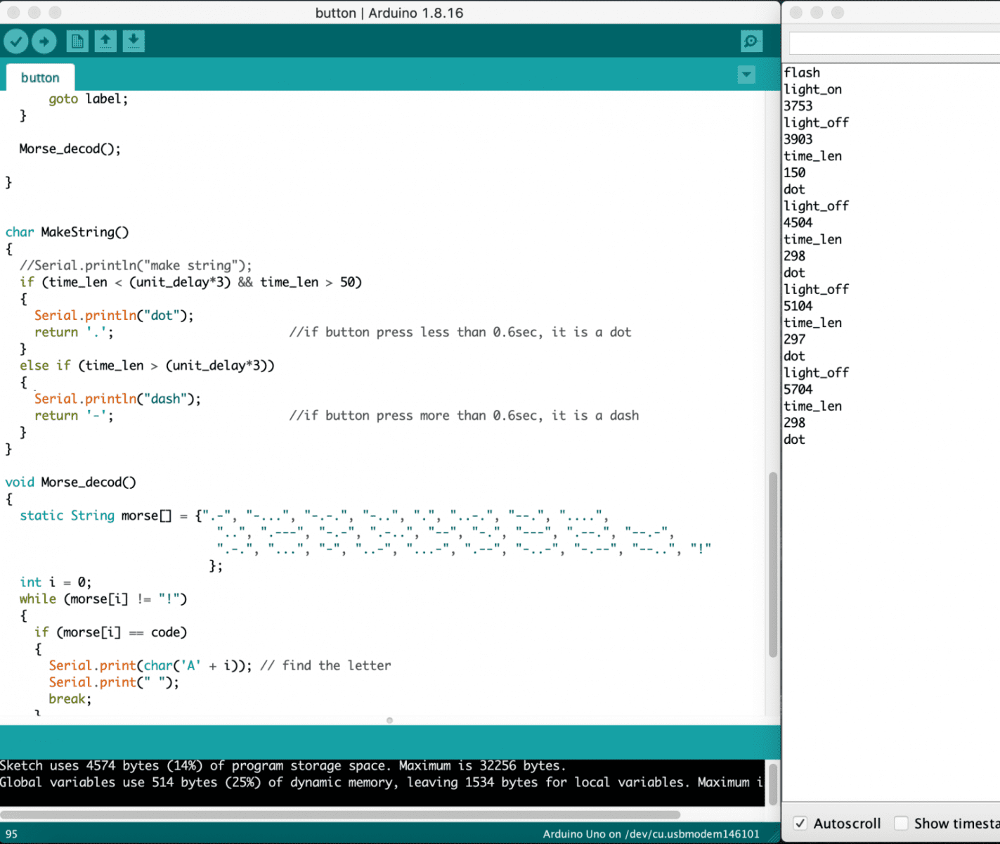
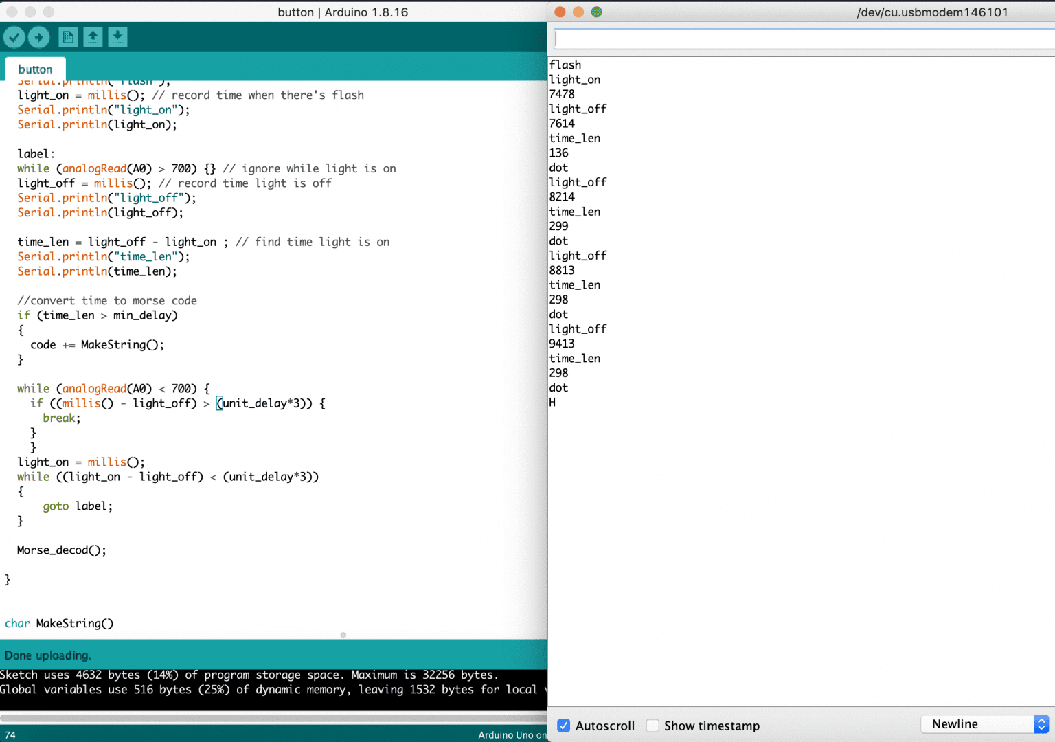
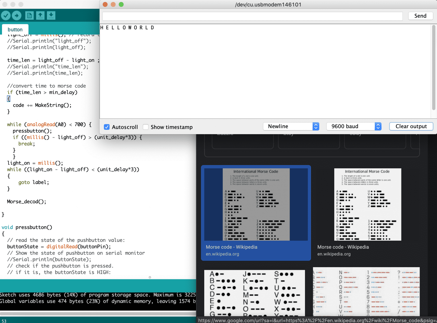
3. Afterward, I streamlined the output display to only show the pres_len value and whether it’s converted to a dot or a dash. To test the code’s functionality, I used a morse code app to flash the light and represent the letter “H” (dot dot dot dot). The output demonstrated that the code effectively converts the duration the light is on into either a dot or a dash. However, I noticed an issue with the pres_len value for the first morse code. It appears to be too large, resulting in the morse code being converted to a dash instead of a dot. This discrepancy arises because the pres_time is recorded the moment I execute the code, as the first while loop is skipped (analog value initially remains below 700 as no light is on).
4. To address the issue, I introduced an additional while loop before the label function to wait until the analog value is below 700, effectively holding the code until a light signal is detected. I then incorporated the line “pres_time = millis()” to start recording the time when the first light signal occurs. Additionally, I included “light_on” and “light_off” statements to monitor when the pres_time (timestamp for when light is on) and rel_time (timestamp for when light is off) are recorded. To keep track of the values for pres_time, rel_time, and time_len, I printed them out. However, upon reviewing the output, it became evident that the code did not record for the first signal.
Since I was still struggling to grasp the logic behind the existing code, I opted to create a completely different void loop to receive input from the photoresistor. Additionally, I introduced supporting functions while retaining the original function responsible for converting morse code to the corresponding letters, just as the website had done. To streamline the process, I decided to write a pseudocode first before diving into the actual code implementation. This approach helped me plan the structure and logic of the new code more efficiently.
Pseudocode:
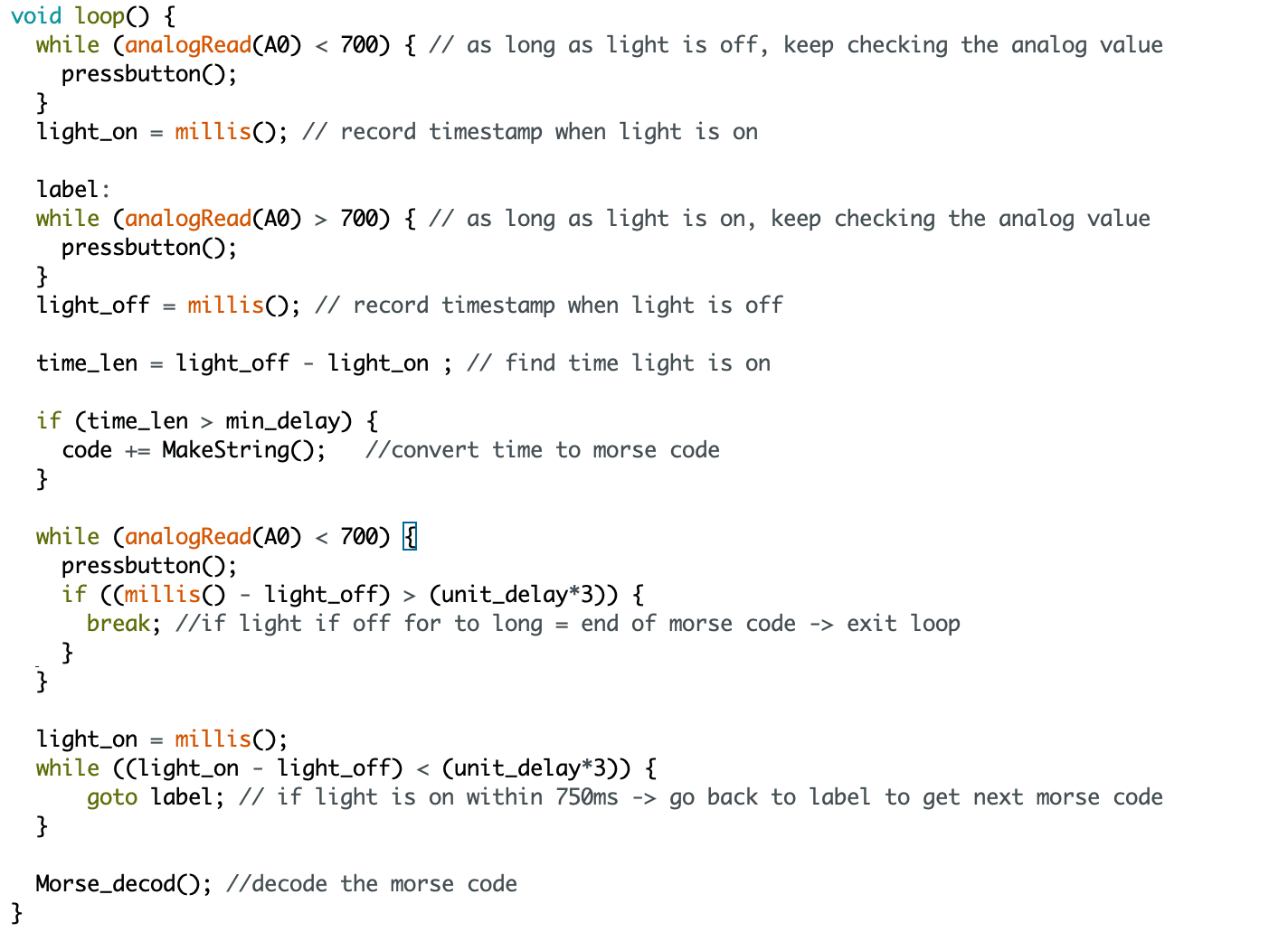
- The code utilizes a while loop to remain idle until a light signal is detected.
- After detecting the light signal, the code records the timestamp and stores it in the time_on variable.
- While the light signal is active, the code enters another while loop and remains idle.
- After the light signal turns off, the code records the timestamp and stores it in the time_off variable.
- Calculate the time length by subtracting the timestamp of when the light turned on from the timestamp of when it turned off.
- Transform the time length into a dot or a dash representation.
- During the period when the light is off, calculate its duration. If the light remains off for more than 750ms, it indicates the end of the morse code sequence, leading to an exit from the while loop for converting the morse code into a letter.
I incorporated several print statements to indicate when the light is turned on/off and display the corresponding timestamps. Additionally, I included the time_len and the morse code (dot or dash) to verify if the time difference is reasonable and if the conversion is accurate. With these modifications, the new code successfully addresses the issue where the first signal was not recorded.
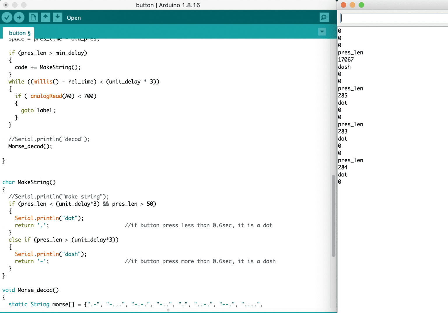
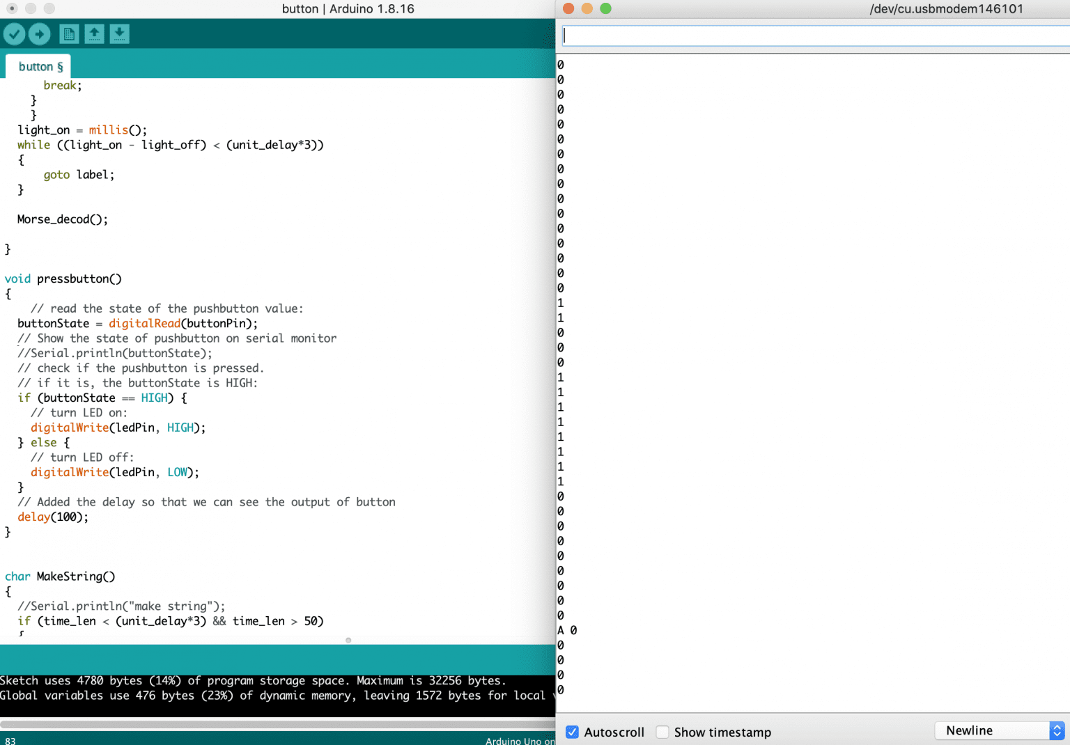
I created a custom function called “pressbutton” and integrated it into the two while loops. This allowed me to simulate pressing the button while the code is waiting for changes in the analog value. Additionally, I included print statements to display the button state (1 for pressed and 0 for not pressed) and the letter translated from the morse code. To test the functionality, I pressed the button to input the morse code for the letter “A” (dot dash). As observed in the output, the button was pressed briefly (two 1s), followed by a period of no button press (three 0s), and then pressed again for a longer duration (eight 1s). After a brief delay to confirm the end of the morse code, the code successfully converted the morse code to the corresponding letter “A” and displayed it in the output.
My code:

My attempt at learning to make morse code:
Challenges
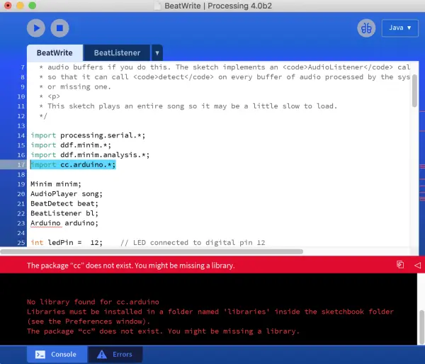
- Initially, I had the idea of creating a project where LEDs would synchronize with a song’s tune. I came across a code online that allowed the LEDs to flash based on an MP3 file of any chosen song. The steps on the website seemed comprehensive and straightforward, leading me to select this project. However, when I set up the circuit, I encountered difficulties in running the code. The website suggested using a different software called Processing to code for the Arduino Uno. My main challenge was locating the specific folders that were required to import the Arduino libraries into Processing.After successfully importing the libraries, I encountered errors indicating that certain libraries were still missing, such as ddf.minim. My research revealed that the website utilized an older version (2.0) of Processing, where these libraries were already integrated. In an attempt to resolve the issue, I downloaded various libraries and organized them in the appropriate folders for the newest version (4.0) of Processing. Unfortunately, the code continued to encounter problems and wouldn’t run successfully.In an effort to overcome the obstacles, I decided to revert to the oldest version (2.2) of Processing that I could find, hoping for compatibility. However, even with this version, the code remained incompatible. Faced with these challenges, I had to abandon the project and look for an alternative one to pursue.
- After settling on the idea of creating a Morse Code Decoder, I encountered difficulties in constructing the circuit, especially when incorporating the photoresistor. I found myself constantly mixing up the pins and wires during this process.
- Due to the continuous changes and debugging in the code, the Arduino Uno was running for extended periods, causing it to overheat and fail to upload the code at times. To prevent this issue, I had to reset the Arduino Uno periodically.
- It took me quite some time and effort to understand the code from the website and debug it to make it work with my circuit. Although I encountered challenges, the code provided on the website was still valuable as it introduced me to useful built-in functions like millis() and label, which I could utilize in my own code.
Improvements
- Create a decoder capable of handling numeric inputs as well.
- The decoder should incorporate a mechanism to consider the duration of the light being off, enabling it to distinguish between letters and words. For example, if the light is off for 250ms, it signifies the same letter; if it’s off for 500ms, it represents the next letter in the same word; and if it’s off for 750ms, it indicates the next letter in the next word. Presently, the decoder displays all the letters together without any spacing, making it difficult to differentiate between different words.
What I learned
This assignment proved to be a challenging and somewhat nerve-wracking experience, making my Halloween weekend quite eventful. However, as I persisted and successfully got the code to work, it turned out to be a highly enjoyable and rewarding endeavor. Through this project, I gained more confidence in my coding and electrical circuit skills, merging the knowledge from my coding and circuit classes into a practical Arduino application.
Applying the theories I learned to create this Morse Code Decoder was a delightful experience. The Arduino Website played a crucial role in guiding me, especially with understanding how to utilize different components effectively. Discovering the ‘label’ function was a game-changer as it allowed me to loop back to specific points in my code, simplifying the process and avoiding unnecessary complexity.
Moreover, encountering the erratic behavior of the LED without the pull-up or pull-down resistor was an eye-opener. It was surprising to witness how such a small component could impact the overall functionality of the circuit. All in all, despite the initial challenges, completing this project has been a valuable learning journey that has deepened my understanding and appreciation for Arduino projects.
Considering my experience with the photoresistor, I see a practical application for Arduino in my daily life. I’m interested in connecting the Arduino Uno board to the light in my room to create an automated system. This setup would enable the light to turn on automatically when it gets dark, enhancing convenience and eliminating the need for manual operation.
To further enhance energy efficiency, I plan to incorporate a Passive Infra-Red (PIR) sensor into the system. This PIR sensor will detect the movement of objects that emit infrared (IR) light, particularly human bodies. By integrating this feature, the light will only activate when the PIR sensor detects motion, preventing unnecessary energy consumption when the room is unoccupied.
Overall, I believe these implementations will not only streamline the lighting control in my room but also contribute to energy conservation and a more efficient living environment.
- What is the purpose of the photoresistor in the project?
The photoresistor detects light intensity changes so the code can measure how long the LED or external flashlight is on and interpret dots and dashes. - How is the button wired to avoid a floating pin?
The button uses a 10k ohm pull-down resistor: 3.3V to one side of the button, the other side to Arduino pin 2 and to ground through the 10k resistor. - Can the LED be controlled by the button in this circuit?
Yes; Pin 13 is connected to the LED anode and the cathode goes to ground through a 330 ohm resistor, and the code turns the LED on when the button state is HIGH. - What analog threshold value indicates the LED is on?
The author observed analogRead around 600 in room light and about 900 with the LED on, so they set a threshold of 700 to determine on versus off. - How does the code distinguish between a dot and a dash?
The code measures how long the analog value remains above the threshold using millis, then converts the measured time length into a dot or dash based on timing rules. - How does the project detect the end of a Morse character or word?
The code checks the duration the light is off; if it remains off longer than 750 ms it treats that as the end of the Morse sequence to convert to a letter. - What debugging steps helped resolve the initial missed first signal?
The author added a pre-wait loop until analog value is below threshold, set pres_time = millis() when the first signal appears, and added print statements to trace timestamps and states. - Did the author reuse code from online sources?
Yes; the author combined insights and functions from Arduino website examples (including millis and a label function) and then rewrote the main loop with pseudocode to handle the photoresistor input. - What were common challenges encountered during the build?
Challenges included wiring confusion when integrating the photoresistor, Arduino overheating from long debug runs, and compatibility issues when attempting a separate LED-sync-with-music project. - What improvements does the author plan for the decoder?
Planned improvements include supporting numeric inputs and refining off-duration timing to place spaces between letters and words properly.