Summary of Pimp My Zoomobil using Arduino
The author modified a Playmobil Zoomobil to add LEDs, a motor, a servo, and remote control using an Arduino, Tamya gearbox, and other off-the-shelf parts. They describe disassembling and prepping the chassis, mounting the gearbox by cutting the chassis and suspending the gearbox with sheet metal, adapting wheels, and addressing motor electrical noise with capacitors. The project evolved through prototyping on an Uno to a final Nano-based build.
Parts used in the Playmobil Zoomobil Mod:
- Playmobil Zoomobil (Playmobil 4855)
- Arduino Uno (for prototyping)
- Arduino Nano (for final product)
- Breadboard (for prototyping)
- Tamya Single Gearbox 4-Speed
- 2 hubs and wheels compatible with Tamya axle
- L293D H-Bridge IC
- SG90R Servo
- Colored LEDs with resistors
- Capacitors (for motor noise suppression)
- Mini Remote Control
- IR Sensor
- 2 x 3-AA switched battery holders
- Solderable circuit board (approx. 6.5cm x 4cm)
- 3 screw-down breadboard-ready power connectors (or barrel connector sockets)
- Female headers (for Nano, LED connectors, IR sensor)
- 3-pin male header (for servo)
- IC chip socket for H-Bridge (optional)
- Sheet aluminum and cutters
- Dremel tool with cutting disks
- Solder and soldering gun
- Hot glue gun
- Assorted screws, nuts, bolts, standoffs, wire, pliers, screwdrivers, wire-strippers, wire cutters
- Miscellaneous plastic pieces from other projects
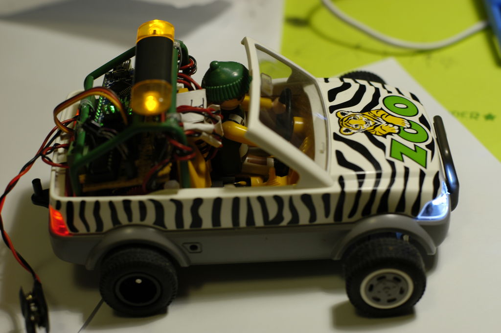
I recently put together the Playmobil Zoomobil for my kids. As I was busy snapping all the pieces together, I became more and more convinced that this cart had been made to have lights. It’s hard for me to believe the original product designers at Playmobil created this without lights in mind.
A lot of the Playmobil vehicles are like this, but the Zoomobil is a perfect example of what I mean: all the places which would be lights on a real car are actually made from clear plastic, as opposed to decals or opaque plastic, and even had spaces behind or within them. Why would Playmobil do this if they weren’t actually thinking about putting an LED there? So, I decided to dress it up a little. And, while I was at it, I thought I’d also add a motor, a servo and remote control to move it around. And, no, I didn’t take my kids’ toy away from them: I bought my own.
This was my first project using an Arduino, really my first electronics project ever, so be nice in the comments.
The finished product is pictured above.
Read on to find out how I did it.
Step 1: Parts List
Most of the following parts can be found very easily on Amazon or Adafruit as well as many other electronics parts websites: other than the Zoomobil itself all the parts are “off the shelf” and almost certainly could be replaced by other, equivalent parts. If you want to modify a Zoomobil, buy it wherever you can find it since it’s been discontinued by Playmobil.
- Playmobil Zoomobil (search EBay/Amazon: “Playmobil 4855” or “Playmobil Zoomobil” or “Zoomobile”)
- Arduino Uno and breadboard for planning, prototyping, programming and debugging
- Arduino Nano to use in final product
- Tamya Single Gearbox 4-Speed
- 2 x hubs and wheels which fit the Tamya axle
- L293D HBridge IC
- SG90R Servo
- Colored LEDs w/resistors
- Capacitors
- Mini Remote Control
- IR Sensor
- 2 x 3-AA switched battery holders
- Solderable circuit board, cut down to approx. 6.5cm x 4cm (Frys)
- 3 x screw-down, bread-board-ready power connectors, although, if I did it again, I’d probably replace the two battery inputs with barrel connector sockets. (Amazon/Adafruit)
- Female headers to socket the Nano, the LED connectors and the IR Sensor
- 3-pin male header (for the Servo)
- Dremel tool with cutting disks
- IC Chip Socket for the H-Bridge (if desired)
- Sheet aluminum and cutters
- Solder/soldering gun
- Hot glue gun
- Assorted screws, nuts, bolts, standoffs, wire, pliers, screwdrivers, wire-strippers, wire cutters, etc.
- Miscellaneous plastic pieces from other projects
Step 2: Body/Chassis Prep
The first thing I had to do was modify some of the click-tabs which held the body to the chassis. I left the tab itself, but used a knife to shave off the small piece at the end which click-locked the tab into place. This allowed the two pieces to stay together, but without locking. It’s a real pain to pull the two pieces apart if you don’t do this. They actually stay together fairly well even without the lock pieces.
I also hot-glued the clear plastic of the headlights-piece and the red plastic of the taillights-piece into place. The pieces kept falling out as I played with the body of the cart and were in constant danger of loss or damage.
Step 3: The Motor and Gearbox
So, let’s get started with the motor and gearbox. The most easily-available gearbox I could find was the Tamya “Single Gearbox (4-Speed)”. It’s really cheap (about $7) and easy to order over Amazon as well as many other places. It allows you to assemble the gearbox in 4 different ways, varying from slow-but-powerful to super-fast-but-weak. I originally used the slowest setting (the “A” option in the instructions), but eventually removed and rebuilt it in the next-faster configuration (“B”): the cart didn’t need all that power, and at the slowest speed it wouldn’t impress anyone. That change tripled the top speed, which was enough for this cart.
The biggest problem I faced with this gearbox was that the axle comes out of the middle of the gearbox. In order for the wheels to fit into the wheel wells in the Zoomobil easily, I needed a gearbox where the axle is at the bottom of the gearbox; this would allow me to secure the gearbox to the bottom of the chassis, and extend the axle out the sides. At the time I wasn’t able to find a gearbox like this (although since then I’ve been made aware of one: Tamya Universal Gearbox Assembly. I can’t actually say how well this would work, but it looks like it would).
In order to use the 4-speed Tamya gearbox, I considered a number of different configurations, including
- set the gearbox above the back of the cart, with its wheels driving the the Zoomobil’s wheels by friction,
- set the gearbox with the motor “in the air” above the back of the mobile,
- attach the gearbox to the underside of the chassis, making the cart look “jacked up”,
- as well as a number of others.
None of these configurations worked for me. In the end, it was clear that, in order to get the axle in the right place, I had to cut a gearbox-shaped hole in the bottom of the cart’s chassis and set the gearbox into it. I cut the bottom of the chassis using my trusty Dremel cutter. I used sheet metal (to secure it from below) and narrow, long screws (from above) to “suspend” the gearbox in the correct place, so that the wheels fit into the wheel-well of the vehicle. The sheet metal below the gearbox had the added benefit of protecting the motor and gears.
I couldn’t figure out any easy way to attach the original wheel hubs to the new axle. So, instead I used some hubs and wheels which were made for the Tamya gearbox. I didn’t like that the hubs’ rubber wheels didn’t match the front wheels of the cart, though, so I popped them off and replaced them with the rubber from the original cart’s wheels. The fit was a little sloppy at first, but never caused any problems. I thought also about painting the hubs white, to match the front (original) hubs, but never got around to it.
All this left about 1mm clearance under the cart. As long as the cart is only driven on hard surfaces, this isn’t a problem.
One other very important point. In my prototype circuit, with my full-sized Arduino Uno and breadboard, whenever I got the motor up to a higher speed, the circuit would “freeze” in a particular state. In essence, it shut down or reset the Arduino. After some research on-line, I realized this was actually a rather well-known problem: motor noise. At higher speeds, the cheap motor’s brushes were feeding so much electronic noise back into the circuit that it was shutting down the Arduino. The solution was to solder a set of very low-value capacitors across the motor terminals and housing. I followed these instructions at Beam-Wiki and my troubles went away. I needed to use the 3-capacitor solution.
For more detail: Pimp My Zoomobil using Arduino
- Why are the Zoomobil light locations clear and hollow?
The article suggests Playmobil designed those areas as clear and with spaces behind them, implying they were likely intended to accommodate lights. - What gearbox was used to drive the Zoomobil?
The project used a Tamya Single Gearbox 4-Speed configured in the B option for higher speed. - How was the Tamya gearbox mounted inside the Zoomobil?
The author cut a gearbox-shaped hole in the chassis, set the gearbox into it, and suspended it using sheet metal and narrow long screws. - How were the Zoomobil wheels adapted to the Tamya axle?
The builder used Tamya-compatible hubs and wheels, removed their rubber, and fitted the original Zoomobil rubber tire material onto those hubs. - What problem occurred when running the motor at high speed during prototyping?
The Arduino would freeze or reset due to electrical noise from the motor brushes interfering with the circuit. - How was the motor noise issue resolved?
The author soldered a set of low-value capacitors across the motor terminals and housing following a 3-capacitor solution from Beam-Wiki. - Which Arduino was used for the final installation?
An Arduino Nano was used in the final product after prototyping with an Arduino Uno. - Did the modified Zoomobil maintain playable appearance and clearance?
The gearbox installation left about 1 mm clearance under the cart, acceptable for driving on hard surfaces, and the author preserved the vehicle appearance by placing components under the chassis.