Summary of PI PICO BECOMES SRAM FOR 1981 EDUCATIONAL COMPUTER
Michael Wessel used a Raspberry Pi Pico to emulate a 2114 SRAM chip for a 1981 Busch 2090 educational computer. He handled voltage differences using passive level shifting (adding resistors to account for the Busch 2090’s 33 kΩ pulldowns) instead of direct 5V connections. The PicoRAM runs at the system’s 500 kHz clock, includes real-time blinkenlights, and the Pico code is available on GitHub. Michael plans a PCB and additional runtime RAM modifications; the approach should work with other systems that used 2114 chips.
Parts used in the PicoRAM for Busch 2090:
- Raspberry Pi Pico
- Passive resistors for level shifting (additional resistors to match 33 kΩ pulldowns)
- Level shifter circuits (tested, but passive resistor approach used)
- Wiring to connect address lines (A0–A9)
- Wiring to connect data lines (D0–D3)
- Connections for Write Enable and Chip Select signals
- Blinkenlights (LEDs and associated wiring/drivers)
- Optional PCB for final assembly (planned)
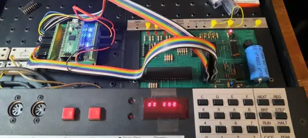
Ever since the Raspberry Pi Pico was introduced in early 2021 we’ve seen the tiny Pi being used for an astonishing variety of applications. It has powered countless clocks, gadgets, games, and accessories for all kinds of computers old and new. [Michael Wessel] has recently added an interesting new application in the “old computer” category, by turning a Pico into a 2114 SRAM emulator for his Busch 2090, an educational computer system from 1981.
The pinout of the classic 2114 SRAM chip is quite simple: ten address lines, four data lines, Write Enable and Chip Select. Since the 3.3 V Pico is more or less 5V tolerant, you could directly connect these signals to its GPIO ports, but [Michael] considered it more reliable to use level shifters between the two voltage domains. He experimented with a few standard level shifter circuits, but quickly realized he had to take the 33 kΩ pulldown resistors on the Busch 2090’s address bus into account. By just adding a couple of resistors to the Pico’s ports he could make completely passive level shifters, which worked just fine since the system’s clock frequency is only 500 kHz.
[Michael] demonstrates his RAM replacement in the video below, with a neat set of blinkenlights showing the data being shuttled around in real time. He has plans to make a proper PCB for his project, as well as to enable all kinds of neat features by modifying the system’s RAM in real time. This is of course not limited to the Busch 2090: the 2114 chip was widely used in the 1980s, so the PicoRAM can probably be used in many other systems of the era. Code for the Pi is available on GitHub if you’re interested in trying this for yourself. If you’d like to find out what programming a Busch 2090 feels like, you can emulate one using an Arduino.Source: PI PICO BECOMES SRAM FOR 1981 EDUCATIONAL COMPUTER
- Can a Raspberry Pi Pico emulate a 2114 SRAM for the Busch 2090?
Yes. Michael Wessel used a Pico to emulate a 2114 SRAM for the Busch 2090. - How were voltage differences handled between the 3.3 V Pico and the 5 V system?
By using passive level shifting with added resistors to account for the Busch 2090’s 33 kΩ pulldown resistors. - Did the project require active level shifter ICs?
No. Michael tested standard level shifters but ultimately used passive resistor-based level shifting successfully. - What clock frequency does the Busch 2090 run that the PicoRAM needs to support?
The system’s clock frequency is 500 kHz. - Are the Pico code and resources available for others to try?
Yes. The code for the Pico is available on GitHub. - Can this PicoRAM approach be used with other vintage systems?
Probably. The 2114 was widely used, so PicoRAM can likely be used in many other systems of the era. - What additional features did Michael plan for the project?
He planned a proper PCB and enabling real-time RAM modifications with added features.