
Summary of Origami Interactive Kinetic Art
This project builds a small kinetic interactive origami installation inspired by Diffusion Choir, using 3D‑printed parts, an Arduino Uno, ultrasonic sensors, and micro servos to make paper blooms that open when an object comes within about 1 meter. The author provides STL/3dm files, assembly and folding guidance, wiring notes, and warns about power limitations and servo stress during testing.
Parts used in the Origami Interactive Kinetic Art:
- Arduino Uno
- 4 Ultrasonic sensors (HC-SR04 used)
- 4 9G micro servo motors (non-continuous)
- Jump wires
- Breadboard (for testing)
- AC/DC adapter for Arduino Uno
- 4 white paper sheets (letter size, thin recommended)
- Scotch mounting putty (for installation)
- Main_gearHolder.stl (3D printed)
- Main_gearWithHole.stl (4x, 3D printed)
- Servo_holder.stl (3D printed)
- Servo_gear.stl (3D printed)
- Servo_pusherPlunger.stl (3D printed)
- Padbase.stl (3D printed)
- Super glue or hot glue
- Skewer sticks
- Soldering tip (for melting/plastic fitting)
Kinetic Interactive Arts? These concept of moving arts and interacting arts are not new to you, but most of the interesting and massive size pieces are almost always located in private companies or corporations. I was inspired by the piece “Diffusion Choir” located in a tech atrium of a company in Boston, and I wanted to make a small scale project. I love art (public art), electronics, and stuff that moves so this is a great opportunity for me to hand on all of them in a single project.
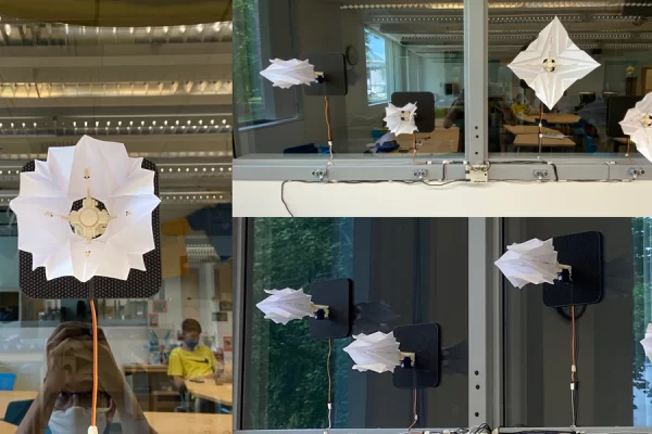
This project involves 3D printing pieces, and majority of the main components I designed by myself so few free to modify and adjust the 3D printing model. I mainly use Rhino 3D so if you want to change the model, please check out my files at the 3D printing section. While you are reading this instructable, if you are planning to follow my steps, I would warn you about the limited resources as I did not keep track of all the components. I was experimenting within the project to make each piece working as I was intended. I encourage you to do the same thing and a lot things can be learned while making it by yourself.
Have fun and do not destroy a lot of servo motors like I did :>
Movin’ on!
Supplies
You will need the following for the main part of the project, you may want to figure it our by yourself on how to install the piece in your place.
– 1 Arduino Uno
– 4 Ultra Sensors (I used HC-SR04)
– 4 9G Micro Servo motors (not the continuous one, but if you want modify the 3D models + code, the project can be better)
– Jump wires
– 1 Breadboard (mainly for testing, I would put the breadboard away for the long-term installation)
– 1 AC/DC Adapter for Arduino Uno
– 4 White Paper (letter size – the thinner the paper the better the result)
For installation, I used Scotch Mounting putty (great stuff for hanging on window)
Step 1: What Does It Look Like?
Here is a quick video on how this thing would turn out.
The mechanism activate when someone/object is closed to it (in this project, if less than (<) 1 meter, the origami will blooms.
Step 2: Schematic of the Project (general)
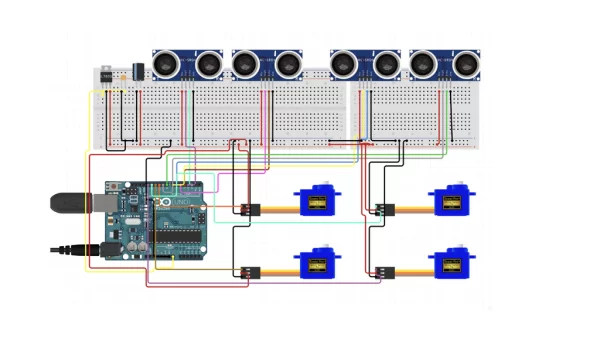
*Feel free to adjust the circuit*
I planed to relying on Arduino Uno power supply (it was a bit glitchy in the project if you use the USB cable to test run the project – try to upload the code to Arduino and use the Adapter Power instead) (I will explain details on why the glitch happens later)
Arduino Uno has 13 digital gates (try not to use gate 0 and 1 because if those gate received signal, the signal could change the code saved in your Uno, they are Serial Ports (USART)) and the project will take up full 12 remained in Uno digital gates, which is perfect.
By these order gates 2-3 are for echo-trig of the ultra-sensor, I may want to repeat that 3+ times for 3 other ultra sensors (4-5, 6-7, 8-9). From gates 10-11-12-13, they are for servos (in order) 1-2-3-4. Each of the ultra sensors are related to one of the servo motors.
You can use the power setup to supply the components like in the schematic, but what I used was parallel circuit to supply them (which is not great and the current is not strong enough to run all 4 at the same time, and that is why the glitch happens)
Step 3: 3D Printing
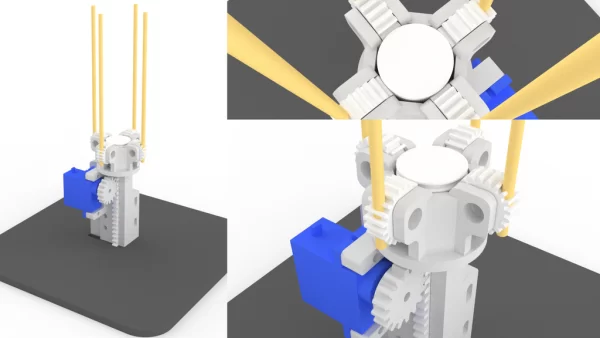
The joy of 3D design *talking in sarcastic tone*, these models that you are seeing here are not the first design, they are all my 4th design within this project.
If you 3D printing and the products seems not really fit that is because I design that would fit the 3D printers I used (Original PRUSA i3 MK3S printers). The design files are all in perfect size (try not to change it). You can use the 3dm from Rhino3D to make change to the models. If you don’t have Rhino, you can try the Evaluation Software Rhino 3D.
Get stl files here (you will get linked to Google Drive for these files)
3dm file is also in the link above.
For a set of the kinetic blooming piece, you will have to print:
– 1 main_gearHolder.stl
– 4 main_gearWithHole.stl
– 1 servo_holder.stl
– 1 servo_gear.stl
– 1 servo_pusherPlunger.stl
– 1 padbase.stl
Step 4: Assembling 3D Pieces
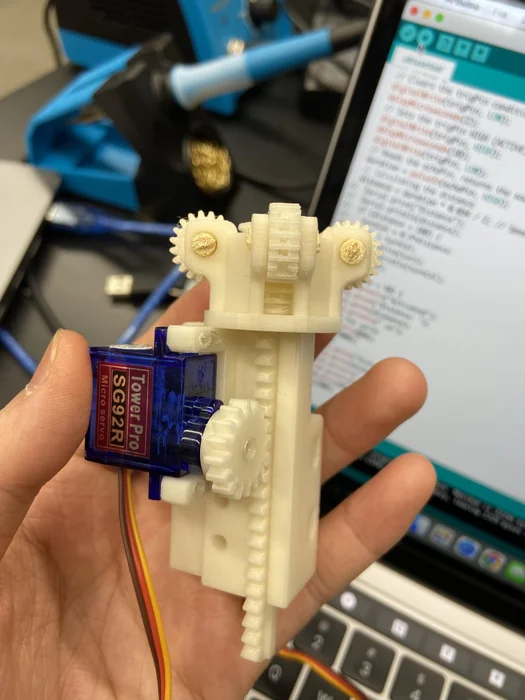
After printing, you can try to connect them.
I connect the main_gearHolder to the servo_holder by using solder tip to melt the plastic and stick them together (also trying to aim somehow the gear_pusherPlunger to fit in with the servo_holder, because if you make a slight off-position the pusher will not catch the gears). Better, you can use super glue to connect 2 pieces of plastic together.
Using the cheap tips of the chopstick I can assemble the gears into the main_gearHolder. Snap off the hanging plastic pieces that is used to snap on the servo motor gear, push that piece into the servo_gear. You may find it will not fit properly, my trick was using the solder tip to melt the plastic around the inner rim.
To get the white piece stick on the padbase, I snapped off the extra part of the pusher and using hot glue to stick it on to the base (make sure you position to fit the hole on the base where the servo wire will go, check the 3rd pictures to see what I mean)
Using skewer sticks to plug in the hole in the gear (4th picture).
Step 5: Folding the Papers
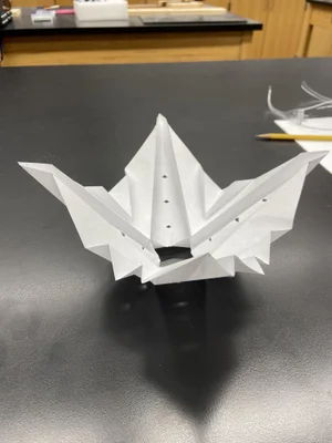
This is the trickiest part as the fold is depending on you. I designed this fold to fit the opening mechanism of the servo, because the 9G Micro Servo is not a powerful component to handling large force (yes opening the paper and closing paper can require substantial N to open and keep it open and closing it). The servo motors will make noise when there is some applying force against its spinning motion.
Use the picture 1-2-3 to be your references of your fold. The hole in the middle of the paper is 3.5 x 3.5 cm. I was planing to make a video on how to fold this piece but it will add more complication in my writing process. I will upload the video sometime soon.
Also, you need to make 4 of these folds (not a lot but the measuring part and the folding part can take quite a lot of time) ask your friends to help you :)))
- What activates the origami blooms?
The mechanism activates when someone or an object is closer than about 1 meter, causing the origami to bloom. - Which Arduino pins are used for sensors and servos?
Digital pins 2-9 are used for ultrasonic sensor trig and echo pairs (2-3, 4-5, 6-7, 8-9) and pins 10-13 are used for servos 1-4. - Can I use the Arduino USB power for this project?
The author warns USB power can be glitchy; use the AC/DC adapter power instead and upload code before using adapter power. - What 3D files do I need to print for one set?
Print 1 main_gearHolder, 4 main_gearWithHole, 1 servo_holder, 1 servo_gear, 1 servo_pusherPlunger, and 1 padbase. - What type of servos should I use?
Use 9G micro servos that are not continuous rotation; continuous servos would require modifying 3D models and code. - How are 3D pieces assembled together?
The author used a soldering tip to melt and join parts or super glue, and used chopstick tips and skewers to install gears and pushers. - How should the paper be prepared?
Use thin white letter-size paper folded per the provided reference; hole in the middle should be 3.5 x 3.5 cm and make four folded pieces. - Why did the project experience glitches when running all servos?
Because the parallel power setup did not supply enough current for all four servos simultaneously, causing glitches. - Where can I modify the 3D models?
The author designed models in Rhino 3D and provided 3dm files; modify them using Rhino 3D or its evaluation software.
