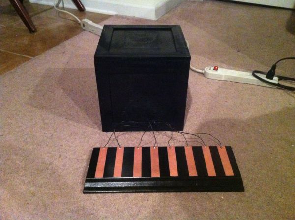
The Octo-phonic Synthesizer is a polyphonic synthesizer that is able to produce eight tones that in the end, creates a musical scale. Inspiration for this creation came from this project. I like to think of it as an electronic organ. I used the core foundation of blinkyblinky’s idea, but also focused more in detail to the craftsmanship of the housing of the actual synthesizer and the other parts. This project is made possible by using the Arduino micro-controller. Joe Marshall wrote the code for this project.
[box color=”#985D00″ bg=”#FFF8CB” font=”verdana” fontsize=”14 ” radius=”20 ” border=”#985D12″ float=”right” head=”Major Components in Project” headbg=”#FFEB70″ headcolor=”#985D00″]
PARTS/TOOLS NEEDED
– Arduino Uno micro-controller
– Copper plating of some kind I used copper-plated fiberglass boards, since they can be cut relatively easily)
– Something to use as the base unit for the synthesizer (I used a cut of a floor molding)
– Epoxy (I used 5-minute epoxy)
– Headers (1 six-pin male header, 1 two-pin male header, 1 4-pin male header)
– 1 barrel plug-to-9-volt-battery coupling
– 1 9-volt battery
– sandpaper
– wire
– speaker(s)
– utility knife
– box of some kind to house arduino and speaker (I used a wooden, craft storage box)
– spray paint
– soldering gun
– solder
– velcro strips
[/box]
Step 1: Copper Keys
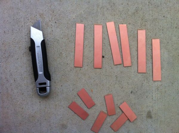
Cut your copper plates to the size that you desire. Since I was trying to make something similar in size to piano keys, I cut mine about 2 cm wide, by about 10 cm long. However, as long as all of your 8 copper keys can fit on your base unit, the size is up to you. Once you cut your copper keys to size, take a medium-grade sandpaper and sand the rough edges so the keys are smooth to the touch.
Step 2: Base
Depending on the size of your copper keys, use a base that is large enough for the keys to be placed on with room in between. I used a 14-inch cut of floor molding. I chose the floor molding because it would fit my keys and the look was appealing as well. If there are any rough edges to your base (if you had cut it), sand it down to a nice, smooth look. Then, spray paint the base to a color of your choosing. I chose black for that simple, elegant look.
Step 3: Soldering the Headers
Take your wire and cut 8, identical-in-length wires. Mine were about 11 inches long each. (If you are using different colored wire, but will like to ultimately have the wire be the same color, I advise painting them now. I learned the hard way and had to painstakingly paint the wires after i soldered keys to my base.) Strip each end. Taking one end of the wire, solder the wire to the end of the copper key. Do this for all 8 copper keys. Take 2 of the keys, and solder them to the 2-pin male header. Take the remaining 6 keys and solder them to the 6-pin male header.
Step 4: Place and glue the keys to the base
Place all the keys on the base to decide the ending placement of the keys. Mark the spot for each key on the base, while allowing space in between each key to avoid a short. Make sure that you place the keys attached to the 2-pin header on the far left, then going from left to right, the other keys in order so that they are soldered to on the 6-pin header. This is to create the musical scale. Using the epoxy, dab a small amount to the underside of each key, and immediately place the keys on their designated spot. On the arduino, the 2-pin header will go in DIgital Input 6 & 7, and the 6-pin header will go in Analog Input 0-5.
Step 5: The Speaker
Strip the input wire of your speaker to separate the positive (+) and negative (-) wires from each other. I found out which one was which by taking off the plastic encasement of the speaker, and looking at the actual metal part of the speaker, where each wire is soldered to it. In my case, the red wire was positive, and the white wire was negative. Allowing for some overall wire length from the speaker, solder the ends of the positive and negative wires to the farthest left pin and farthest right pin of a 4-pin male header. On the arduino, the positive pin will go into Digital Input 11, and the negative pin to ground (GND), next to the Digital Inputs.
For more detail: The Octo-phonic Synthesizer