Hi guys, my name is Pedro Castelani and I’m bringing you my first instructable: building a two way radio with arduino for, well, whatever you need it for.
In this project, we will make two seperate circuits which will act as both reciever and transmitter. The most important components are two arduino boards (all of them work) and two nrf24 transciever modules. In my case, I control a servo with a potentiometer from the other arduino and send the voltages of a two cell lipo battery back to the first one.
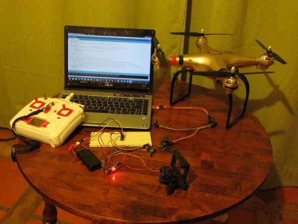
I intend to use it as an add-one for my drone, which does not possess telemetry nor servo gimbal control. You can, however, use it for other things, such as building your own quadcopter, plane, rc car, etc. From the code supplied you can also make any modifications you want according to your needs. I will also try to explain how to modify it correctly (which took me some time to learn by myself, as I was accustomed to another kind of use for the nrf24 chip).
Step 1: Materials
To begin our project, we need to know all the parts needed. Below is a list of the basic ones needed. I bought most of them at a local electronics shop where I live, so I wont be able to recommend you any place to buy them. You could try Amazon, or any other place. I am not saying you should order them there, but its just a suggestion.
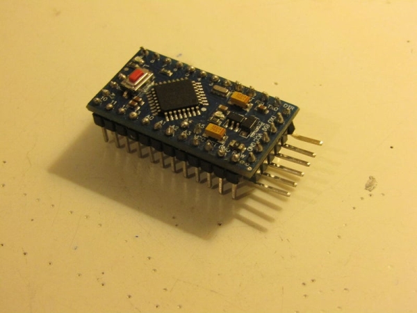
- Two Arduino boards (anyone should work. I have two arduino pro mini, which I like a lot because they have 13 digital pins and 8 analog, while the Uno only has 6 analog ones).
- Two Nrf24 modules. There are some with external antennas which have greater transmission range. Choose the ones you most like.
- Female-Female and Female-Male jumper cables.
- Prototyping board.
- Arduino Programmer (for arduino pro mini, if you have one with usb connection you wont need it).
- Arduino IDE (Software). Download from here.
- In my case, I also used:
- Servo. Anyone you can get. I like the SG90, a small one designed for arduino.
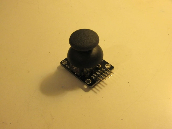
- Potentiometer (between 10k and 20k ohms). Can be bought at a local electronics shop or you can use the joystick made for arduino. There are a few images of the ones I have. I also got one from a broken drone rc controller, just to give you a few ideas
- 4 equal normal resistors. I used 10k ones I got from my grandfather’s house. I am using them as voltage dividers.
- Small copper pad perfboard (which I also got from my grandpa) for soldering the resistors together.
- Pins. Used to connect the jumper cables from the arduino to the resistors easily.
- 2s lipo battery. I use it to power one of my arduinos. The resistors are connected to it and read its voltages. I intend my arduino to be connected to my drone’s 2s battery, since it wont need an external power source and at the same time tell me how much battery is remaining.
- Soldering Iron and solder. Needed to solder the resistors, the perfboard and the pins together.
Step 2: Function and Code
Once all the materials have been mentioned, let’s start talking about the function of the modules.
- How it works: Lets call one arduino “A” and the other one “B”. In my case, after programming both, I connected them to their corresponding radio chip and added the potentiometer to arduino A and the resistors and servo to arduino B. Module A sends values to B and moves the Servo. B reads the voltages of the 2s battery and sends them back to A. Then the whole circle begins again. Since A recieves values that are not expressed mechanicaly, it is connected to the programmer, through which we can read them with a serial monitor (included in the Arduino IDE).
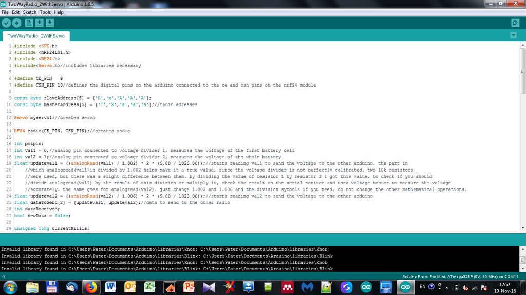
- Code: I call the sketch for arduino A (connected with the programmer and the potentiometer) TwoWayRadio_1, and the sketch for arduino B TwoWayRadio_2WithServo.
TwoWayRadio_1 and TwoWayRadio_2WithServo can be found just below this paragraph. There is an explanation inside each code just to make everything easier to understand.
Step 3: Soldering Modules: Voltage Divider and Potentiometer
This step is optional, since you might just want to use the potentiometer-joystick designed specifically for arduino and use another module instead of the voltage divider. I, however, planned everything (codes included) for these modules.
- Potentiometer:
- This part is just about the easiest one in the soldering step. You will just have to solder some jumper cables to your potentiometer. If you want, you can first solder the potentiometer to the perfboard and then solder some of the pins. When you need to use it, just connect the jumper cables to the arduino and then to the pins on the perfboard. When not in use, you may remove the cables and use them for another project. If, however, you do as I did, you can leave the potentiometer soldered directly to the cables.
- If you are doing as I did, get three female-female jumper cables, cut of one of the tips and remove the insulation there, leaving a small piece of copper wiring on each wire.
- Heat up your soldering iron and solder the modified jumpers to you potentiometers pins. If you can, try to get different colors so that you can remeber which one is vcc, gnd and the “signal” one (the middle one). Connect these cables to the corresponding analog pins on the arduino. There are some images at the beginning of the step on how it ended looking. The potentiometer is not a regular one, it is actually a small wheel which had five pins. Took me some time to find out which was which. Try to do it easier and use a regular potentiometer as shown in the MATERIALS step.
- If you are soldering it to a perfboard, get the potentiometer and the perfboard and solder them together with your soldering iron.
- Get the pins (three) and place them in the most convenient way. Use solder to make a connection between each pin and the potentiometer pins. Do not make a connection between more than two pins or it will not work (it will act as a short circuit).
- Get some female-female or female-male jumper wires and connect them from your arduino to your new potentiometer module (remember which is which).
2. Voltage Divider:
- This part is a bit more complicated. You will need to get the four resistors, five pins and the perfboard. I designed the code to be used for a 2s battery (two cell), but you could also use it for a 1s by changing the arduino sketch a bit and the hardware. I included pictures of two voltage dividers I made, one with only 2 resistors (for 1s batteries) and one with four (you guessed it: 2s batteries).
- Let’s start with the 2s one. I do not have images of the building process since I started witing this instructable a good while after having finished soldering it. I do include images of the final result, so I will try to be as clear as possible.
- Start by getting the perfboard and 5 pins. Solder them close to the side and do not let them touch each other.
- Solder the resistors as shown in the last image at the start of the step (the small circuit diagram). The connections between each resistor and pin is made with solder. Try to occupy the least space possible.
- When you are done, it should look something like the pictures of the finished voltage divider I posted above.
- The 1s Voltage divider is basically the same, with the exception that you only use three pins and two resistors. I included images of how it looks when finished. Just look at the diagram for the 2s one and imagine it without the signal wire 1, the middle wire, and resistors r2 and r3 and there, you have it!
- So, if you want a 1s voltage divider, it might just be a little more complicated than just using a 2s one.
Source: NRF24 Two-Way Radio for Telemetry