Summary of Location Tracking “Weasley Clock”
This article details the construction of a DIY "Weasley Clock" inspired by Harry Potter, which tracks family members' locations via servos. The project involves designing a plywood face with transferred icons, 3D printing arrows and mounts, wiring an ESP8266 board to servos, and configuring Adafruit IO for cloud data. Location updates are automated on Android using the Tasker app, which triggers MQTT messages to update the clock's hands based on GPS proximity.
Parts used in the Weasley Clock:
- Plywood sheet
- Matte gel medium
- Wemos D1 mini (ESP8266 board)
- SG90 micro servo
- 5V DC power supply with 2.1 mm barrel jack
- 2.1 mm DC socket with screw terminals
- Wire
- 3D printer filament
As with so many other people, I’ve always been a massive Harry Potter fan. One of the coolest magical items in the series was almost certainly the Weasley family clock that had a hand for each family member, and moved to reflect their location. I had wanted to make my own version of the clock for a long time and there were lots of different designs online. Unfortunately, many of them were expensive to make, overcomplicated, or just not very effective. In the end, I made my own design and was really happy with how it turned out. You can use a laser engraver to create the background images but I present a way for adding the icons to the clock without the need for one as well!
As with any good coding experience, I ended up basing my design off of some previous work. This design was inspired by an awesome tutorial on Adafruit (https://learn.adafruit.com/gmailbox).
Supplies
Supplies
1 x Plywood sheet (size depends on how large you want your final clock to be)
Matte gel medium (if you don’t have access to a laser engraver)
1 x Wemos D1 mini (any other ESP8266 board would do but this one is cheap and widely available)
1 x SG90 micro servo (add an additional servo for every extra person you want to include on the clock)
1 x 5V DC power supply with 2.1 mm barrel jack
1 x 2.1 mm DC socket with screw terminals
Wire
3D printer filament
Tools
Soldering iron
3D printer
Laser printer
Drill
Hacksaw blade
Laser engraver (optional)
Step 1: Designing the Clock Face
First we’ll design the board that everything attaches to. You can either cut your plywood to your desired size, or else lots of hardware stores will cut things to the size you want for a small fee when you buy the wood.
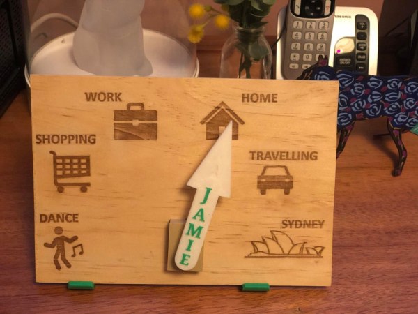
To design the icons for the clock face, I recommend using something straightforward like Powerpoint, or you can use a free online service like Canva.com. Either way, you can choose icons to represent all of the locations that you want to track and arrange in the order that they’ll sit on the clock face. I have attached one of my designs as a guide but you’ll obviously need to update the size and icons for your own preferences.
We want to print our design but we need to make sure the design is MIRRORED before we print it (see the uploaded file for an example). The reason is that we are going to transfer this design to our plywood and the design will transfer back-to-front. You also need to make sure that the design is printed on a laser printer. This technique will NOT work if you print the design using an inkjet printer. Most public libraries and big office supply stores tend to have laser printers that you can print from for cheap.
Once you print the design, cut away the blank space and liberally brush some of the matte gel medium onto the paper on the printed side. Press the paper onto the plywood with the design facing down. Make sure there are no wrinkles in the paper and that the design is in the right location. Wipe up any gel that spills out the side and leave the plywood to dry for 12 hours.
Once the gel has dried, use a damp cloth and lightly rub the paper. This should soak the paper and make it fall away, leaving the pattern affixed to the wood. Be careful not to rub too hard as you might rub off the design as well.
If you have access to a laser cutter, you could use that as an alternative to burn a design into your wood.
Step 2: 3D Printing
The pieces we want to 3D print are the arrow with a name on it, and the mounts for the electronics. If you want a slightly neater look, you can also print off the servo cover.The files for the electronic mounts and servo cover are attached, and a blank arrow is attached for you to customise with your name. If you aren’t confident with 3D design, I recommend using Tinkercad online. It is very straightforward to use and you can simply import the blank arrow, add a text object with your name, and position the two however you want on top of each other so that the text pokes up above the arrow by about 3-5 mm.
When printing your arrow, you might want to have the name be a different colour as in my photos. If you don’t have a fancy dual extruder printer, set your printer to pause when it starts printing the text, and change your filament out so that the text prints in a different colour. This pause can be set in Cura under “Extensions – Post Processing – Modify G-Code – Pause at Height”.
Step 3: Wiring
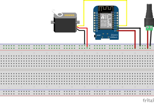
The wiring here is pretty simple. Servos use a lot of current, which is why we are powering it straight from the 5V power supply as opposed to powering it from a pin on the Wemos board. Depending on whether you want one arrow or two on your clock, follow the relevant wiring diagram. The barrel jack is connected to our 5V power supply.
It’s also important to note here that the pin numbers written on the board don’t match up with the pin numbers that we reference in our Arduino code. The pin numbers that we’ll use in the code match up with the GPIO numbers seen in the attached pinout diagram. In case you don’t want to follow the diagram, the connections are as follows:
d1 mini GND -> GND/barrel jack –
d1 mini 5V -> 5V/barrel jack +
d1 mini D2 -> servo1 signal
d1 mini D4 -> servo2 signal
servos GND -> GND/barrel jack –
servos VCC -> 5V/barrel jack +
Step 4: Adafruit IO
The clock works by sending location information from your phone to a cloud service called Adafruit IO using the MQTT protocol. This means we need to create an account at https://io.adafruit.com/. Once you’ve signed up for an account, create a feed called “Locations”. This should be fairly self explanatory and if not, there are some other great tutorials out there created by Adafruit.
Next, you’ll need to write down your username, and your Adafruit IO Key. You can find this key by pressing the “Adafruit IO Key” button in the top right corner of your feed. We’ll use this information in the next step.
Step 5: Modifying and Uploading Code
The good part of the Wemos mini board is that we can upload code to it from the Arduino IDE. The bad news is that there’s a bit of setup to go through before we can get to that point. Fortunately, lots of other people have written guides for this so instead of echoing what they have said, you can read it for yourself HERE.
The only extra thing we’ll need to add is the Adafruit IO library. When you’re adding the “ESP8266 Microgear” library, also search for “Adafruit IO Arduino” and install the latest version (3.7.0 at the time of writing). It might tell you that there are other libraries that this library depends on so go ahead and let it install those too.
The code you need is attached here (the single user code is attached here, the two user code is attached in the next step). You’ll need to save the two files in a folder with the same name as the .ino file and then you’ll need to make some modifications:
- In config.h, use the information you wrote down in the previous step to update IO_USERNAME and IO_KEY with your Adafruit IO username and key respectively.
- A few lines below, update WIFI_SSID and WIFI_PASS with the name and password of your home wifi network.
- In the main code file, you will need to update the angles at which each of your icons occur. These angles are listed in the #define statements near the top of the code. If you have added any locations that are different to those in the code template, you’ll also need to add those and define them with their own angles. If you add or remove any locations, you’ll also need to update the “if else” statements at the bottom of the code to include those new locations. The pattern should be quite clear from the existing code. These angles won’t necessarily be perfect but we can test them and refine them once everything is mounted in place.
With all of these changes made, you’re ready to upload your code to the board. Follow the instructions in the linked tutorial if you want more info about this.
Step 6: Two Person Code
The code you need for two users is uploaded here. Follow the same steps as mentioned in the previous step to modify this code before uploading.
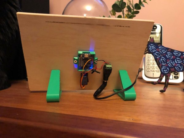
Step 7: Mounting the Components
Hold your servo in the position where you want the arrow to be and trace the outside of the servo with a pencil. Drill a hole in this rectangular region and use a hacksaw blade to cut out the rest of the rectangular region. If you have a jig saw, this step will go much quicker but it’s not essential. Once you’ve made a rectangular hole, the servo should fit into it snugly and you can use the screws that should have come with your servo to hold it in place. If you printed the servo cover in the previous step, you can slip it over the front of the servo now.
Take one of the servo arm attachments that should have been included with your servo and glue it to the underside of your 3D printed arrow. Once the glue is dried, this arm should easily attach to the servo to keep the arrow in place.
Next, screw or glue the 3D printed electronics mounts onto the back of your plywood board and place the electronics in place so they can’t fall out. Now that your code is uploaded and the arrow is attached, you can plug in the clock and test whether the angles in your code are correct. To test this, turn on your clock and open up your locations feed in Adafruit IO on your computer/phone. You can manually enter data to change your location by pressing the “add data” on your location feed and typing in the location you want to move the arrow to. Update the angles in your code as appropriate and reupload the code to confirm that all of your angles are correct.
Step 8: Setup Phone for Location Tracking
We now have a clock that can display a location based upon the value it reads from the Adafruit IO feed. What we still need to do is figure out how to update that location feed depending on where we are. I initially tried using the IFTTT app but found that their location trigger feature is not very reliable. Instead, I chose to use the Tasker app. The app costs about $5 in the Google Play Store but has heaps of awesome functionality. Install the Tasker app on your phone as well as the Tasker MQTT Plugin (also available for download from the Google Play Store).
Next, we need to set up tasks to update our location. This can be a little time consuming but once it’s done, you won’t need to change anything again. Open the Tasker app and go to the “Tasks” tab. Press the plus button and give your task a name. I suggest calling it “Home”, “Work”, etc. for extra clarity. Once you’ve created the task, hit the plus button in the bottom right corner and select “Plugin – MQTT Publisher”. Click on the pencil button next to the “Configuration” bar and enter the following settings:
- Server address: io.adafruit.com
- Port: 8883
- Client ID: Leave blank
- SSL/TLS: Ticked
- Username: Your Adafruit IO username
- Password: Your Adafruit IO key
- Topic: “Adafruit IO username”/f/Locations (replace “Locations” with the name of the feed you want to upload to if it is different)
- Message: The name of a location (HOME, WORK, TRAVELLING, etc.)
- QoS1 selected
- Retain Flag: Not ticked
You’ll need to make one of these profiles for each of the locations on your clock. Once all of these tasks are created, go back to the “Profiles” tab. Click the plus button to create a new profile and select the location option. Here, you can type in a location and define a radius in which a selected task will execute. As an example, put in the location of your home and make it execute the home task when this profile is activated. You can also add an exit task to your profiles which will execute when you leave the defined area.
Add a profile for each of your locations and ensure that the exit task for all of these locations is the “Travelling” task. This means that if you are ever in an area that hasn’t been defined, the clock will show you as travelling. You can have different locations execute the same task as well. For example, I have multiple shopping centre locations as separate profiles but they all execute the “Shopping” task.
Once all of the profiles have been added to your phone, your clock will now be fully functional however I recommend updating some settings to prevent the app from draining too much of your battery life.
The Tasker app can drain a lot of battery depending on how often you tell it to check your location so we will tell it to check less often.
- Click on the three dots in the top right corner of the app and hit “Preferences”.
- Make sure you are on the “Monitor” tab, scroll to the “BT Scan Seconds” setting and change the value to 120 (if you later find you’re draining too much battery, you can make this and below values larger to check less often).
- Do the same with “Wifi Scan Seconds” (change to 120), “GPS Check Seconds” (change to 100), “Network Location Check Seconds” (change to 100), and “GPS Timeout Seconds” (90).
- Scroll to the “Display Off Monitoring” section and change “All Checks Seconds” to 200, with a Timeout of 20.
- In the “General Monitoring” section, change both timeouts to 5.
Tasker sets alarms to know when to check for location changes. This unfortunately means it will display in your notifications as though an alarm is set. To remove this, go to the top of the Monitor tab and change “Use Reliable Alarms” to “Never”.
The last thing to change is to make sure your phone doesn’t stop the app from working when the screen is turned off.
- Open your phone’s settings app and navigate to the apps menu (different for every phone but on mine it is “Apps and Notification”
- Go through and find Tasker in the list of apps
- Open the battery/power option (could be under “Advanced”) and look for something like “Battery optimization”.
- Ensure this is set to “Not optimized”. This stops the phone from closing the software when the screen is turned off
- While you’re here, you can also turn off all notifications for the app as you won’t need them.
Source: Location Tracking “Weasley Clock”
- Can I use an inkjet printer for the clock face design?
No, the technique will not work if you print the design using an inkjet printer; it must be printed on a laser printer. - How do I transfer the design to the wood without a laser engraver?
You can brush matte gel medium onto the printed paper, press it face down on the plywood, let it dry for 12 hours, and then rub off the paper with a damp cloth. - Does the pin number on the Wemos board match the code reference?
No, the pin numbers written on the board do not match up with the pin numbers referenced in the Arduino code; you must use the GPIO numbers from the pinout diagram. - What is the best way to track location for the clock?
The author recommends using the Tasker app with the Tasker MQTT Plugin because the IFTTT location trigger feature was found to be unreliable. - How do I prevent the Tasker app from draining my battery?
You should increase scan seconds values in the Preferences menu and set Battery optimization to Not optimized for the app. - Can I add more than one person to the clock?
Yes, you need to add an additional SG90 micro servo for every extra person you want to include on the clock. - What happens if I am in an area that has not been defined?
If you are in an area that has not been defined, the clock will show you as Travelling. - Do I need a dual extruder printer to print multi-colored names?
No, if you do not have a fancy dual extruder printer, you can set your printer to pause when it starts printing the text to change the filament color manually.