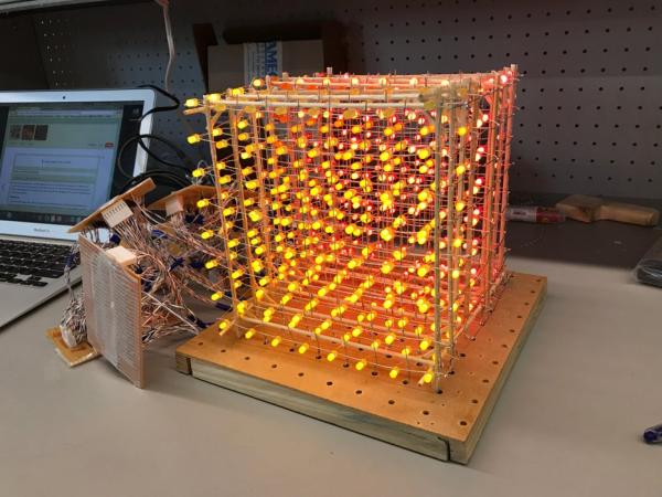
In this project, you will build an 8x8x8 LED cube as a display. After building the cube and learning the code basics, you will be able to write your own display animations. It is a great visual for scientific purposes and it will be a nice decorative addition to your room! During the process of the cube-building, you will acquire a whole slew of basic electronics skills, which paves the way for more complex projects in the future.
This is my individual project for the Electronics course, and it took about five weeks. I spent 12 hours on this project per week, and I had access to the parts and tools typically found in a college electronics lab. It might also be good to know that, even though the workload is not a piece of cake, no hands-on expertise is required. Instead, you’ll gain much experience and learn from your own mistakes along the way.
Disclaimer: I borrowed the design and the code from Kevin Darrah (http://www.kevindarrah.com/?cat=99) who built an 8x8x8 RGB cube (thus tripling the work!). The waveform display is my own work. I strongly recommend watching all his LED videos before you start the project! They are extremely helpful in understanding how everything works, which is crucial for this complicated project! I gave brief explanations about the circuitry and the general architecture when I discuss the circuit connections and the code, so feel free to jump to that part first to gain a theoretical understanding:)
Step 1: Part List
- single-color DIFFUSED LEDs x512 with ~30 spares (You might notice that I used three colors myself. This is originally designed to help reflect the waveform amplitude (e.g. red means higher amplitude), but I didn’t solder the slices correctly, so eventually I just treated them as the same. If you are still interested in making color variations in the vertical direction, please read notes on the vertical slices step:))
- PC boards, medium x7 and small x2 (These are the ones available in my lab, but please feel free to adjust the size depending on what’s readily available to you! Please read the circuitry section for your reference. I found that for beginners, PCBs without any connected strips are more accommodating, mainly because you can add and cut connections at will. De-soldering can be tricky!)
- NPN 2N3904 transistors x72
- 1k resistors x 150
- 100 Ohm resistors x 72
- P-channel MOSFETs IRF9Z34 x8 plus 8 clip-on heat sinks
- 100 micro Farads capacitors x8
- 74HC595 shift registers x9
- Arduino Uno + screw shield (I used a proto-screwshield R3 kit)
- Wire with insulation of 8 colors (I highly recommend using different colors! You will have a lot of wires right next to each other, and the colors really help when we check the circuit.)
- 5V 2.8A power supply (as long as your power supply current limit is higher than 64*(current through 1 LED), it should work fine:))
- wire terminals
- Molex headers with 8 pins and 6 pins.
- Molex wire housing with 8-pins and 6-pins (the quantity of these will be different depending on your PCB size and your circuit design, so please read the whole Instructable (particularly the circuitry part) before deciding on the number you need:))
- Solder
- Bare copper wire (to be on the safe side, prepare 50m of this)
- Large wood board (roughly 9 inch on each side)
- 12 inch wooden skewers (optional; if you find a way to make straight wires, you don’t need this)
- scotch tape
- long nails x16
Tools
- Soldering iron
- wire cutter
- pliers
- glue gun (optional; if you find a way to make straight wires, you don’t need this)
- crimper
- heat sink clamps x2 (alligator clips work as well)
- wire stripper
Step 2: Making LED Rows
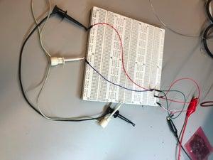
First and foremost, test all the LEDs! I breadboarded up a circuit with an LED and an 100 Ohm resistor. I then tested one LED at a time and added that in parallel with the other LED. We want to discard 1) broken LEDs, 2) LEDs with the anode and the cathode backwards (you don’t want to just “remember” which one has got it flipped!) 3) dimmer LEDs.
Next, we made the wooden jig, which is also my final mount for the cube. Drill a 8×8 grid with 1 inch between the center of the holes. Select drill bits with a diameter just above the diameter of your LEDs, such that they can fit into the holes and still stay straight. We nailed extra wooden strips to the perimeter, which kept the board surface flat (we used plywood for the board, so it’s got a fair bit of flex to it). In addition, this elevated the areas with the holes such that the LEDs can poke through the holes. Select one side and put two long nails on the same line as the centers of the holes. We’ll tie the wires on these nails.
We can now start to make LED rows! I didn’t find an effective way to make straight wires, so I only un-kinked the wires using a wooden block. Place the wire across the edge of the block; hold the wire down with your thumb on one side of the block and pull the wire through; the edge of the block will un-kink the wire. I recommend putting on a glove to protect your thumb:(
Place 8 LEDs into this row with the long “leg”, the anode, facing one direction. We are going to solder them onto the wire. Note that the plane formed by the anode leg and the cathode leg should be perpendicular to the line of the wire, and the cathode leg should be away from the wire. Tie the wire on a nail and pull it to go across the LEDs until it’s straight and taut. Tie it on the other nail. Adjust the wire height (I noticed a small flat area on the LED leg, and I adjusted the wire such that it’s touching this area for all LEDs). This height is arbitrary, but please be consistent. Keep in mind: 1) the level height difference in your cube is going to be roughly 1 inch (so the wires can’t be too high); 2) the LEDs might break under the heat of the soldering iron (so the wires can’t be too low) (though I haven’t personally experienced any issue from this). Now your wire should be touching the long leg of the all LEDs, forming a cross. Solder the wire and the anode leads and trim the leads afterwards.
In this project, I experimented with two different solder joint contact configuration. One is the cross contact described above, and the other is bending the LED leg such that the contacting wires are parallel. Theoretically, the parallel contact joints are more stress-resistant, but considering how light the LEDs are, the cross joints probably aren’t that detrimental. You will gain a lot of practice soldering the wire and LED legs, so feel free to experiment with different techniques! I used a flat tip soldering iron, and I personally think it offers better control over the solder blobs and a larger heat contact surface area.
After you do the soldering, use the breadboard for the LED-checking to check the connections(important). Clamp the positive lead to the wire and sweep the negative lead through the short LED legs. They should all light up! After we check that they are all fine, gently push the LEDs from below the board to dislocate them and slide the wire up the nails. You can trim away the looped ends, but definitely save some length!
What if my LED doesn’t light up?
First things you might check is whether you got the cathode and the anode flipped. Then try clipping the positive lead to the LED leg instead of the whole wire. If your LED lights up that way, you can re-solder the LED. If your LED still doesn’t light up, replace it with another.
We need to make 64 such LED rows:)
Step 3: Soldering Vertical Slices
As a preview, all the anodes in each layer are connected, and all cathodes in each vertical column are connected. Now we need to make the vertical slices. Remember the two nails we put into the board to tie wires? Now put in 14 more of those in a similar way:) (Caution: file the nail tips well! You will be pressing your fingers around those tips a lot.)
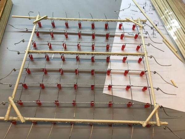
Now place 8 LED rows onto the board and make sure that their legs are facing the same direction. Note that the wires should be parallel to the rows of nails! Push down on the LEDs such that they are all at the same height. If some of the LEDs keep popping out (perhaps due to the curvature in your wire), scotch-tape down the ends to the board. Now, run wires across the nails as before. I could only eyeball the wires to be approximately on the same height, but that’s ok because what you really care about is that the LEDs are at the same height.
Solder the cathode leads onto the wires. You’ll notice that here I used the parallel-contact soldering configuration, and I did find that more solid and better looking than the cross joints, but it was more time consuming, because you need to 1) bend the wires with pliers; 2) make sure that the bent section touches the main wire; 3) bend that section to be at the right height, because your soldering iron will come in at an angle and you need the iron to touch both wires at the same time.
If you want to use different colors at different layers….
Make sure that each of your slices reflects the color scheme. For example, if I wanted the top three layers to be yellow LEDs, the middle two to be orange LEDs and the bottom three to be red LEDs, I’ll place three yellow LED columns, two orange ones and three red ones in that order. Make sure that your color order and the LED orientation is consistent for all eight slices!
Use the breadboard setup to test all the LEDs in each slice. It is definitely easier to re-solder here when your LEDs are secured rather than in the middle of the air.
If your wires aren’t straight on themselves, DON’T pull the slice from the nails just yet! Read the next step.
If you already have straight wires, push the LEDs gently from below and slide the slice from the nails. Don’t trim the ends just yet:)
Step 4: Supporting the Vertical Slices
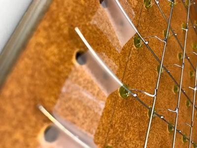
If your wires have some curvature to them, as mine did, we can fix them to be on a flat plane by adding rigid support along the perimeter. I chose 12 inch wooden skewers because they are readily available on Amazon. I glued the skewers on the perimeter and added small pieces in the corners to strengthen the frame. See photos for details. Note that only two skewers are completely attached to the wires, and the other two skewers are above the whole grid. I recommend testing the frame without the corners pieces first. I found that the extra short sticks got in the way of the LEDs when I was stacking the slices up, and the glue joints are probably strong enough to hold the LED grid anyway. If the grid still bulges a little bit, press down on the two un-glued sides and glue the wires to the skewers at several points. Don’t trim away the loose ends just yet! In particular, keep a fair bit of length of skewers on the side that’s going to be at the bottom of the cube, so that we can keep the LEDs off the floor.
Source: LED Cube Display