Summary of Interfacing Flame Sensor with Arduino to Build a Fire Alarm System
This tutorial explains interfacing an infrared flame sensor module with an Arduino to build a fire alarm that lights an LED and sounds a buzzer when a flame is detected. The sensor uses an IR photodiode/phototransistor (YG1006), an LM393 comparator, and an adjustable potentiometer to give a digital output. Arduino reads the sensor on a digital pin, and when flame_detected is HIGH it activates buzzer and LED and logs alerts via Serial. Operating voltage is 3.3–5V and detection covers ~700–1000 nm with ~60° angle.
Parts used in the Fire Alarm System:
- Arduino Uno (or any Arduino board)
- Flame sensor module (infrared, YG1006 based)
- LED
- Buzzer
- Resistor
- Jumper wires
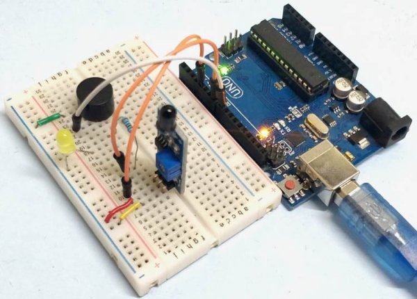
This tutorial discusses how to connect a Flame Sensor to an Arduino and create a Fire Alarm System using the same components. The flame sensor module utilizes a photodiode for light detection and an op-amp to regulate sensitivity. It is utilized for fire detection and gives a STRONG signal when detecting a fire. Arduino interprets the signal, then activates the buzzer and LED to send an alert. The flame sensor utilized in this system is an infrared flame sensor.
Flame Sensor
A flame detector is a sensor that is created to identify and react to the existence of a flame or fire. Reactions to a identified fire vary depending on the setup, but may involve setting off an alarm, shutting off a fuel line (like propane or natural gas), and starting a fire-fighting system.
T
A flame detector is a device made to sense and react to the existence of a flame or fire. Different flame detection methods elicit various responses based on the setup, including triggering an alarm, shutting off a fuel line like propane or natural gas, and initiating a fire suppression system. Some examples include: Ultraviolet detector, near-infrared array detector, infrared (IR) detector, Infrared thermal cameras, UV/IR detector etc.
As fire burns, it gives off a minimal amount of infrared light, which will be detected by the Photodiode (IR receiver) on the sensor module. Next, we utilize an Op-Amp to monitor any fluctuations in voltage at the IR Receiver, so that the output pin (DO) will go to 0V(LOW) if there is a fire detected, and will stay at 5V(HIGH) if there is no fire present.
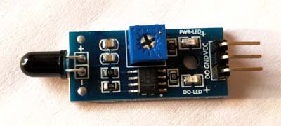
This project involves the utilization of an infrared flame sensor. The YG1006 sensor utilized in this device is a NPN silicon phototransistor known for its high speed and sensitivity. It is capable of sensing infrared light between 700nm and 1000nm and has a detection angle of around 60°. The flame sensor module includes an IR receiver (photodiode), resistor, capacitor, potentiometer, and LM393 comparator all in one integrated circuit. The sensitivity can be changed by adjusting the potentiometer located on the circuit board. The operational voltage ranges from 3.3v to 5v DC, delivering a digital output. A high logic level on the output indicates the existence of a flame or fire. An absence of flame or fire is indicated by a logic low on the output.
The following is the Pin Description for the Flame Sensor Module:
|
Pin |
Description |
|
Vcc |
3.3 – 5V power supply |
|
GND |
Ground |
|
Dout |
Digital output |
Applications of flame sensors
- Hydrogen stations
- Combustion monitors for burners
- Oil and gas pipelines
- Automotive manufacturing facilities
- Nuclear facilities
- Aircraft hangars
- Turbine enclosures
Components Required
- Arduino Uno (any Arduino board can be used)
- Flame sensor
- LED
- Buzzer
- Resistor
- Jumper wires
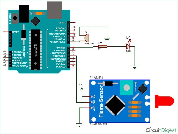
Circuit Diagram
Working of Flame Sensor with Arduino
Arduino Uno is a microcontroller board that is open source and relies on the ATmega328p microcontroller. The Arduino Uno is equipped with 14 digital pins (including 6 PWM outputs), 6 analog inputs, voltage regulators, and has 32KB flash memory, 2KB SRAM, and 1KB EEPROM. It functions at a clock speed of 16MHz. Arduino Uno can communicate with other devices using Serial, I2C, and SPI communication protocols. Below is a description of Arduino Uno’s technical specifications.
|
Microcontroller |
ATmega328p |
|
Operating voltage |
5V |
|
Input Voltage |
7-12V (recommended) |
|
Digital I/O pins |
14 |
|
Analog pins |
6 |
|
Flash memory |
32KB |
|
SRAM |
2KB |
|
EEPROM |
1KB |
|
Clock speed |
16MHz |
The flame sensor identifies fire or flame by detecting the Infrared (IR) wavelength emitted by the flame. It produces a logic 1 output when detecting flame, otherwise it produces a logic 0 output. Arduino Uno monitors the voltage on the sensor’s output pin to trigger actions like turning on the buzzer and LED, and sending an alert.

Also, check our other fire alarm projects:
- Fire Alarm using Thermistor
- Fire Alarm System using AVR Microcontroller
- Arduino Based Fire Fighting Robot
Code explanation
The full Arduino code for this project can be found at the conclusion of this article. The code has been divided into small, meaningful sections and elaborated on.
In this section of the code, we will set up pins for the Flame sensor, LED, and buzzer that are linked to the Arduino. The flame sensor is linked to Arduino’s digital pin 4. The buzzer is attached to digital pin 8 on the Arduino. The LED is attached to Arduino’s digital pin 7.
The digital value obtained from the flame sensor is stored in the variable “flame_detected”. With this value, we can identify if there is a flame present.
int buzzer = 8 ;
int LED = 7 ;
int flame_sensor = 4 ;
int flame_detected ;
In this part of the code, we are going to set the status of digital pins of Arduino and configure
Baud rate for Serial communication with PC for displaying status of flame detection circuit.
void setup()
{
Serial.begin(9600) ;
pinMode(buzzer, OUTPUT) ;
pinMode(LED, OUTPUT) ;
pinMode(flame_sensor, INPUT) ;
}
This line of code reads the digital output from flame sensor and stores it in the variable “flame_detected”.
flame_detected = digitalRead(flame_sensor) ;
Based on the value stored in “flame_detected”, we have to turn on the buzzer and LED. In this part of the code, we compare the value stored in “flame_detected” with 0 or 1.
If its equal to 1, it indicates that flame has been detected. We have to turn on buzzer and LED and then display an alert message in Serial monitor of Arduino IDE.
If its equal to 0, then it indicates that no flame has been detected so we have to turn off LED and buzzer. This process is repeated every second to identify the presence of fire or flame.
if (flame_detected == 1)
{
Serial.println(“Flame detected…! take action immediately.”);
digitalWrite(buzzer, HIGH);
digitalWrite(LED, HIGH);
delay(200);
digitalWrite(LED, LOW);
delay(200);
}
else
{
Serial.println(“No flame detected. stay cool”);
digitalWrite(buzzer, LOW);
digitalWrite(LED, LOW);
}
delay(1000);
We have built a fire fighting robot based on this concept, which automatically detect the fire and pump out the water to put down the fire.
Check the complete code and demo Video below.
Read More Information…..
Interfacing Flame Sensor with Arduino to Build a Fire Alarm System
- What type of flame sensor is used in this project?
An infrared flame sensor using a YG1006 phototransistor and photodiode with an LM393 comparator is used. - How does the flame sensor indicate a detected flame?
The sensor provides a digital output that goes to logic 1 (HIGH) when flame is detected and logic 0 (LOW) when no flame is present. - Which Arduino pin is the flame sensor connected to in the example?
The flame sensor digital output is connected to digital pin 4 on the Arduino in the example code. - What actions does the Arduino take when a flame is detected?
When flame_detected equals 1 the Arduino turns on the buzzer and LED, blinks the LED, and prints an alert to the Serial monitor. - How can the sensor sensitivity be adjusted?
Sensitivity is adjusted using the potentiometer on the flame sensor module. - What operating voltage does the flame sensor module require?
The flame sensor operates from 3.3 V to 5 V DC. - What wavelength range can the YG1006 phototransistor detect?
The YG1006 can detect infrared light roughly between 700 nm and 1000 nm. - What components are integrated on the flame sensor module?
The module integrates an IR receiver (photodiode/phototransistor), resistor, capacitor, potentiometer, and an LM393 comparator. - What is the Arduino code behavior when no flame is detected?
If flame_detected is 0 the Arduino turns off the buzzer and LED and prints No flame detected to the Serial monitor.