Hello Guys
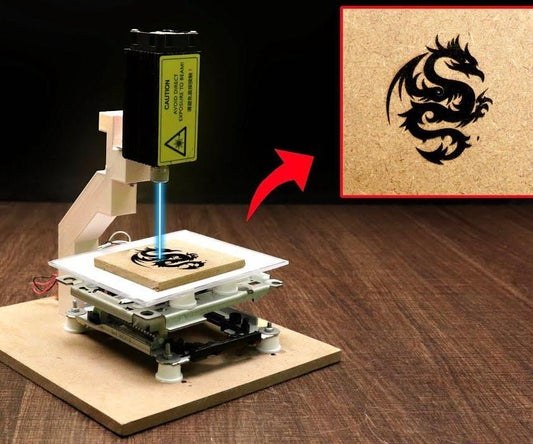
Whats up, In this instructable, I am making an Awesome mini laser engraver from old DVD writers.
It’s very interesting project for any electronics hobbyist & Engineers. You can use this laser engraver machine to make any kind of design, logo, art on the surface like WOOD, MDF, PLYWOOD, VNYL Paper.
Thank You NextPCB:
This project is successfully completed because of the help and support from NextPCB. Guys if you have a PCB project, please visit their website and get exciting discounts and coupons.
Only 0$ for 5-10pcs PCB Prototypes:https://www.nextpcb.com
Register and get $100 from NextPCB: https://www.nextpcb.com/register
See more info about PCB Assembly Capabilities: https://www.nextpcb.com/register
Here are mid-summer sales at NextPCB :
1. Up to 30% off for the PCB orders
2. Up to 20% off for the PCBA orders
Visit my website DiY Projects Lab for More CNC machine i wish you liked it , I got this Laser engraver’s idea from Maggie Shah. Here’s the version of his laser engraver https://www.instructables.com/id/Mini-CNC-Laser-W… .
I remixed his project with my own touch.
Step 1: Here’s the Full Video Tutorial Video
Step 2: Supplies
Parts and Materials Required
- Arduino UNO (with USB cable)
- 2x DVD drive stepper mechanism
- 2x A4988 stepper motor driver modules (or CNC shield)
- Laser with adjustable lens
- 12v 2Amps power supply minimum
- 1x IRFZ44N N-CHANNEL Mosfet ,etc..
Tools List:
- Soldering Iron
- Drill Machine
- Sand paper
- Wire Cutter
- Superglue
- 3D printer
Step 3: What Is CNC ?
CNC (computer numerical control) The system is based on the control of the movements of the work tool in relation to the coordinate axis of the machine, using a computer program benbox executed by a computer.it is necessary to control the movements of the tool in two coordinate axis: the X axis for the longitudinal movements of the carriage and the Z axis for the transverse movements of the tower. servo motors are incorporated in the carriage and turret displacement mechanisms.
AXIS MOVEMENTS
X axis – left to right
Y axis – front to back
Z axis – up and down
3 Axis
Automatic/interactive operation
Milling slots
Drilling holes
Cutting sharp edges
What is Stepper Motor ?
The stepper motor is an electromechanical device that converts a series of electrical impulses into discrete angular displacements, which means that it is capable of advancing a series of step depending on its control inputs. The stepper motor behaves in the same way as a digital-to-analog (D / A) converter and can be driven by pulses from logic systems. Its main applications include a variable frequency motor, brushless DC motor, servo motors and digitally controlled motors
Why do we use stepper motor?
Essentially, stepper motors offer excellent speed control, precise positioning, and repeatability of movement. Additionally, stepper motors are highly reliable since there are no contact brushes in the motor. This minimizes mechanical failure and maximizes the operation lifespan of the motor.
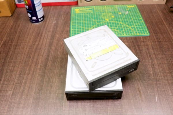
Step 4: DVD Drive Stepper Mechnaism
We need two DVD writers mechanism for this project. One for X-Axis and another one for Y-Axis.
You can find this DVD writer from broken CPU or local hardware shop. I also got from the local hardware shop at very cheap prices.
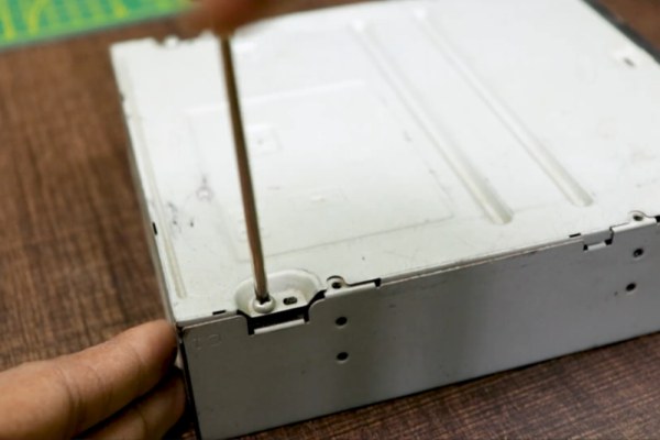
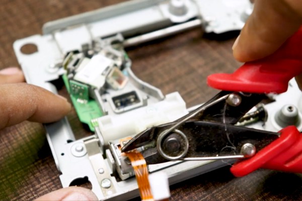
Now its time to disassemble the DVD writers.
- Use Philips head screwdriver to remove all screw.
- Unplugged all the connectors and cables from dvd drive
- Open the disk holder and unscrew the sliding mechanis.
- Detached the Sliding mechanism.
The stepper motors are 4-pin Bipolar Stepper Motor.
Step 5: Wiring of Stepper Motors
Using continuity mode with Multimeter determine
determine 2 Coil, Coil A and Coil B.
I made 2 pairs of wire by selecting colours, one pair for the Coil A and second for the Coil B.
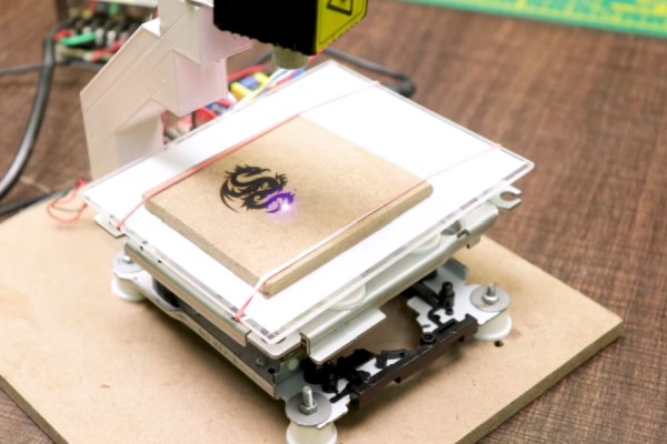
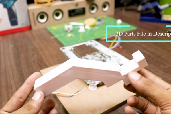
Step 6: Set X-axis and Y-axis Co-ordinates Movement.
I’ve attached the slider of X and Y-axis together in perpendicular to each other, using glue between them. And also attached a 3D printed part piece above it as a working bed.
Step 7: Attach the Laser Holder
Attach the laser holder with bed as i shown in picture above
i have use 3d printed Laser holder you can also print this holder
quite easy and fun. In the laser holder
Step 8: Attach the Laser
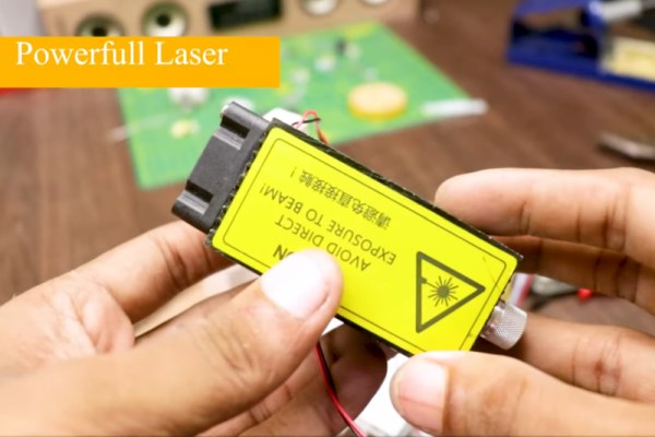
The laser I used is 1W 445NM Laser Module
Now it’s time to attach the laser module.
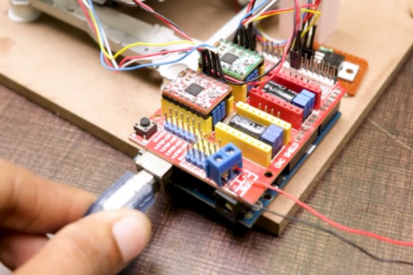
Step 9: The Electronics
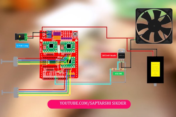
Luckily, the Arduino shield we’re using already has all the inputs and outputs labelled, so it’s very easy to wire everything up. I also made a schematic to help you in the process.
Ready to your all circuit
1) 2 PCs A4988 Stepper Motor Driver
2) Expansion Board A4988 Driver
3)Arduino UNO
First of all take hit sink and stick on A4988 motor Driver.
2 pcs A4988 Stepper motor driver connect on expansion board A4988 driver module, then connect the arduino with expansion board and connect all wiring
The shield also has a built-in micro stepping control – meaning that instead of using full steps or half steps like a large CNC would do, we can make the motors move by 1/16 or 1/32 of a step to make the laser move with the maximal precision possible.
However, the motors will consume more electricity: they will get hot quicker.
To use the micro stepping modes, short some of the mode pins together. Different combinations give different resolutions.
Take a look at the chart for the different configurations possible.
When the shield is programmed, add the A4988 drivers to it and wire up the rest of the electronics.
To find the coils of the stepper motors, use a multimeter. If there’s resistance between the two wires, you have a coil.
On the schematic, the coils are represented by two wires of the same color.
Step 10: STEPPER MOTOR DRIVER A4988
The A4988 is a complete micro stepping motor driver with built-in translator for easy operation. It is designed to operate bipolar stepper motors in full-step, half-step, quarter-step, eighth-step, and sixteenth-step modes, with an output drive capacity of up to 35V and ±2A.
We can control the stepper motor with just 2 pins from our controller, like Arduino: one for controlling the rotation direction and the other for controlling the steps.
Step 11: Benbox Softwer Configuration
Software
Download and Install Benbox
Install Benbox Laser Engraver 3.7.99
1. Download and unzip Benbox
2. Select Benbox and run the setup wizard
3. Download and install the Arduino IDE. https://www.arduino.cc/en/Main/software
4. Click and install CH340 driver.
5. Restart computer
6. Connect the USB cable between computer and engraver.
visit DiyProjectsLab For more info
To install the firmware, click on the lightning symbol at the top of the menu (rightmost icon).
1. Select the appropriate com port.
2. Select nano(328p).
3. Select and install the Lx. Hex firmware.
4. Click install. When the firmware has installed successfully, you will see a green checkmark beside the update firmware title at the top.
The last step is to set up the parameters for the engraver.
1. Click on the blue menu icon at the top right-hand corner of the software.
2. Click on the right arrow underneath the menu icon to access the parameter list.
3. Enter the parameters’ values as depicted in the photo.
This starting spot will correlate to the red arc at the (0,0) position (refer to image).
Draw an simple image using the drawing tools on the left. Press the green start button to start the print. Click the circular laser button with adjust until the beam is sharp.
Source: How to Make Powerfull Laser Engraver