Hello every body, Welcome to this tutorial.
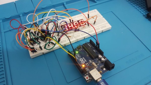
In this tutorial we gonna talk about How to drive a 4-digits 7segment with Arduino using minimum pins.
To do this we are going to use very popular IC called 74HC595. It’s a 8-bits shift register that has 8 separate outputs. the advantage of this chip is that it doesn’t require a complex protocols like I2C or SPI. It just need three GPIOs to control outputs. You can see this IC pinout in below picture:
Step 1: 74HC595 Pinout Description
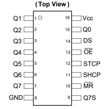
Q0 to Q7 are outputs. DS is data input pin. SHCP is the clock pin and STCP is the pin that let you transfer data to outputs. OE is output enable. a logic 0 on this pin enables the outputs. If you put a logic 1 to this pin the outputs will be Hi-Z or Disconnected, just like an open switch and doesn’t let current to flow through output pins. We connect this pin to GND to make output always available.
MR is master reset pin. A logic 0 will reset the outputs to default state that is logic 0 or 0V. We connect this pin to VCC. Q7S is data output pin. We will explain the usage of this pin in further.
Step 2: Common Anode 4-Digits 7Segment Connections
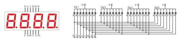
First of all let see the connections and pinout of a 4-digits seven segment. In above picture you can see this connections. It has 12 pins. 7 for displaying digits. 1 for Dot Point and four pins for anode of each digits.
There are two types of seven segments. Common Anode and Common Cathode. In our case we are using Common Anode type. Each digits consist 7 LEDs named from A to G. In common anode type the anode of all LEDs connected together for each digits as you can see in picture. So we should connect Anode to VCC and to turn on each LED we should connect it’s cathode to GND. As the cathode of each digit’s LEDs is common through these four digits, we should multiplex theme.
To display each number we can use below table.
Step 3:
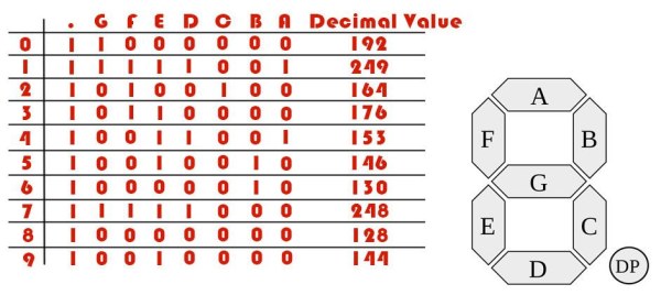
For example to display number 1 we should turn on B and C LEDs and turn off other LEDs. As it is a common anode seven segment we should write 0 to this pins and write 1 to anode pin.
Step 4:
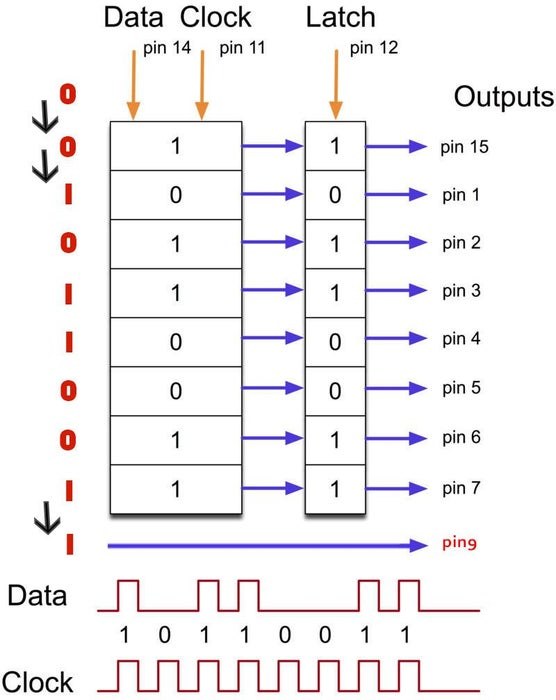
The working procedure of our shift register is shown in above picture.
We put our Serial Data on DS pin and we put our clock on SHCP pin. On clock rising edge the data on DS pin will shift into the 8-bits register of 74HC595 IC. After 8 clocks, our 8-bits data will completely shifted into the register. Then we can put a rising edge pulse on STCP pin and our 8-bits data will go to our output pin.
If we make an extra rising edge clock the first bit that is shifted in will go to Q7S pin and all bits will shift one bit further and new data on DS pin will replace with the last bit.
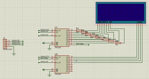
we can use another shift register to make 16 outputs. We should connect Q7S pin of first shift register to DS pin of the second shift register, And connect SHCP and STCP of both of them together.
The final circuit diagram will be like below picture:
Step 5:
Step 6: Arduino Code
You can see full explanation of Schematic, Procedure, and Code’s details on above video.
Source: How to Drive 4-Digits Seven Segment With Arduino Using Just 3 Pins