Summary of How to Build Your Own Anemometer Using Reed Switches, Hall Effect Sensor and Some Scraps on Nodemcu.
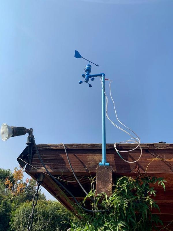
This article details a DIY anemometer and wind vane project using recycled materials like PVC, aluminum tubes, and bottle caps, controlled by an ESP8266 NodeMCU. The device measures wind speed via a Hall Effect sensor counting cup rotations and determines direction using eight reed switches triggered by a neodymium magnet on the wind vane.
Parts used in the DIY Anemometer and Wind Vane:
- 8 x Reed Switches
- 8 x 10 k ohms resistors
- 1 CD4051 Analog Multiplexer
- Neodymium magnet (0.5 x 0.5 cm)
- 10 different colors wires
- Generic PCB
- Ball bearings
- Aluminum tubes (approx 20 cm, 10 cm, and 5 cm)
- PVC pipe (10 cm, 2.5 cm diameter cap, 5 cm diameter caps, and approx 2 meters with T connector)
- Plastic disk and strong plastic piece (20 x 20)
- Ping pong balls (2)
- Wooden or aluminum sticks (approx 12 cm)
- Hall sensor SS49E
- Epoxy Mass and Instant Glue
- ESP8266 NodeMCU
- Solar panel (5V power supply)
In this post, we will learn How to Build Your Own Anemometer Using Reed Switches, Hall Effect Sensor and Some Scraps on Nodemcu. Since I started with the studies of Arduino and the Maker Culture I have liked to build useful devices using junk and scrap pieces such as bottle caps, pieces of PVC, drink cans, etc. I love to give a second life to any piece or any material. A large part of the materials used here is scrap removed from some equipment and recycled.
Part 1 – Hardware
When I started a project of a weather station for my own I realized that the measurement of the intensity and direction of the wind would not be very easy or cheap. After several months I present to you this project that uses mostly recycled materials and very cheap electronic parts easily found in any electronic store.
This post has 2 parts.
Part 1 – Construction of the devices Anemometer and Wind Vane Direction.
Part 2 – The sketch using Arduino IDE for Esp8266 Nodemcu and transmission to ThingSpeak.
See the video to know the final solution.
How to build your own Anemometer using Hall Effect Sensor and Reed Switches
Project description
The anemometer is a device capable of measuring the wind speed and its direction. Using a Hall Effect sensor we will be able to count how many rotations the cups give in a period of time. The intensity of the wind is proportional to the speed of rotation of the axis. With some simple physics equations, you can determine the linear velocity of the wind, at that moment. We will explain all of them in part 2.
And the direction of the wind we will measure through a windshield with a neodymium magnet and reed switches. The vane points in the direction of the wind and the magnet attached to it will connect the reed switches allowing the electric current to pass through the connection (or connections). Circuits that have positive current indicate the direction of the wind, like a compass.
We have 8 circuits that will emulate 16 directions : 4 cardinal and 4 collateral points when 1 switch is activated (N, NE, E, SE, S, SW, W, NW) and when 2 switches are activated simultaneously we have 8 sub collateral points (NNE, ENE, ESE, SSE, SSW, WSW, WNW, NNW).
The wind speed and direction will be calculated and determined by a sketch in the nodemcu. But this will be explained in part 2. Now let’s go to the hardware assembly.
Disclaimer: This anemometer should not be used for professional purposes. It is only for academic or home use.
Note: English is not my natural language. If you find grammatical errors that prevent you from understanding the project, please let me know to correct them. Thank you so much.
How to Build Your Own Anemometer Using Reed Switches, Hall Effect Sensor and Some Scraps on Nodemcu: Steps
Step 1: Bill of Materials
- Wind Vane
8 x Reed Switches
8 x 10 k ohms resistors
10 cm PVC pipe
2 PVC caps 5 cm diameter
1 PVC cap 2.5 cm diameter
1 CD4051 Analog Multiplexer
1 plastic disk
20 x 20 strong plastic piece
1 Neodymium magnet (The dimensions of the magnet must allow two switches to be connected simultaneously. Mine is 0.5 x 0.5 cm and it is doing well.)
10 different colors wires
1 Generic PCB
1 ball bearing with the same diameter of the aluminum tubes
1 aluminum tube approx 20 cm
1 aluminum tube approx 10 cm
1 hose clamp
Epoxy Mass
Instant Glue – cyanoacrylate and sodium bicarbonate
- Anemometer
2 Ping pong balls
4 wooden or aluminum sticks approx 12 cm
1 ball bearing
1 aluminum tube approx 5 cm
3 pieces of wires different colors
1 hall sensor SS49E
1 neodymium magnet
Epoxy Mass and Instant Glue – cyanoacrylate and sodium bicarbonate
2 plastic taps approx 3 a 5 cm diameter
1 PVC cap and 5 cm PVC pipe
1 PVC cap 2.5 cm diameter
- Nodemcu
- Plastic Case for Electronic Projects
- Soldering Iron
- 1 PVC Pipe approx 2 meters and “T” PVC Connector
- 1 PVC 90 degrees connexion
- 5V power supply (I’m using solar panel)
- How does the anemometer measure wind speed?
A Hall Effect sensor counts the rotations of the cups over time, as wind intensity is proportional to the axis rotation speed. - Can this device be used for professional purposes?
No, the article states this anemometer should not be used for professional purposes but only for academic or home use. - What components are used to determine wind direction?
The wind vane uses a neodymium magnet and eight reed switches to emulate 16 directions based on which circuits have positive current. - Does the project require expensive electronic parts?
No, the project uses very cheap electronic parts easily found in any electronic store and mostly recycled materials. - How many directions can the wind vane detect?
The system emulates 16 directions: 4 cardinal points, 4 collateral points, and 8 sub-collateral points. - What type of sensor is used to count cup rotations?
A Hall Effect sensor, specifically the SS49E model, is used to count how many rotations the cups give. - Which microcontroller is used for this project?
The project uses an ESP8266 NodeMCU to calculate wind speed and direction and transmit data. - What kind of power supply is suggested for the 5V requirement?
The author mentions using a solar panel as a 5V power supply.