Summary of Home Automation using Arduino and GSM Module
GSM-based home automation using Arduino lets you control and monitor appliances via SMS. A SIM900 GSM module receives commands; Arduino (using SoftwareSerial on pins 9 and 10) parses SMS to turn devices on/off. Status is shown on a 16×2 JHD162A LCD (4-bit mode, LiquidCrystal library). For demo, three LEDs and a 12V DC motor (driven via BC547 transistor) represent appliances; a micro buzzer signals valid SMS. Hardware serial pins are avoided during development to prevent upload conflicts.
Parts used in the GSM based home automation project:
- Arduino board
- SIM900 GSM module
- 16×2 JHD162A LCD module
- SoftwareSerial library (uses digital pins 9 and 10)
- LiquidCrystal library
- Three LEDs (representing devices)
- 12V DC motor (fourth device)
- BC547 transistor (to drive DC motor)
- Micro buzzer (connected to A4)
- Wiring and supporting circuitry for device interfacing (e.g., resistors, transistors, power supply)
In this article, we are publishing a highly useful home application – GSM based home automation using Arduino. The project consists of a 16×2 LCD module for displaying the status of the home appliances. The status (turn ON or turn OFF) of the connected devices can be changed by sending an SMS from your mobile phone. Upon receiving SMS commands through GSM module, arduino will change the status (turn ON/OFF) of the device that is mentioned in the SMS.
Objectives of the Project
- Send/Monitor the status of the connected devices to a specified mobile number using GSM.
- Change the status (turn ON/OFF) of the device upon receiving commands through SMS.
- Display status of the devices in an LCD using a 16×2 LCD module.
Note: – For demonstration purpose, we are using 3 LED’s to represent 3 different devices. We have also connected a 12Volt dc motor as a 4th device. You can replace these LED’s with actual electrical light bulbs, devices like motor, fan, TV, refrigerator etc. You should use an appropriate supporting circuit to interface these devices to the circuit diagram given below.
Let’s begin to build our project – GSM Based Home Automation Using Arduino.
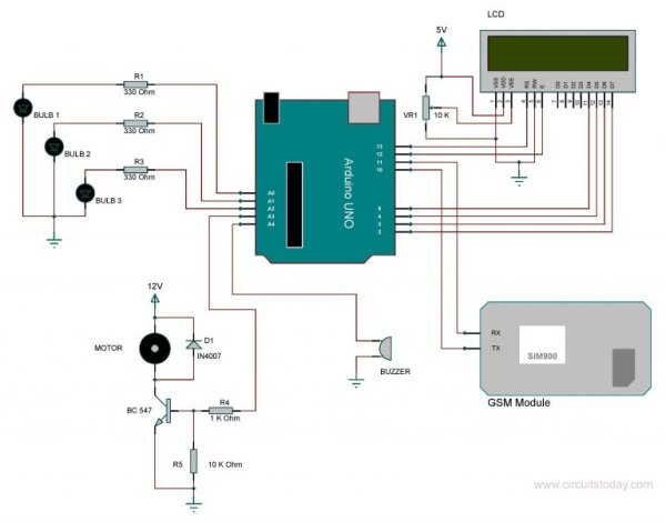
Here we are using SIM900 GSM module. The communication between GSM module and arduino is serial. The problem with this connection is that, while programming Arduino uses serial ports to load the program from the Arduino IDE. If these pins are used in wiring, the program will not be loaded successfully to Arduino. So you have to disconnect wiring in Rx and Tx each time you burn the program to Arduino. Once the program is loaded successfully, you can reconnect these pins and have the system working.
To avoid this difficulty, I am using an alternate method in which two digital pins of Arduino are used for serial communication. We need to select two PWM enabled pins of Arduino for this method. So I choose pins 9 and 10 (which are PWM enabled pins). This method is made possible with the SoftwareSerial Library of Ardunio. SoftwareSerial is a library of Arduino which enables serial data communication through other digital pins of Arduino. The library replicates hardware functions and handles the task of serial communication. This will help the programmer to use hardware serial pins for debugging purpose.
Note: – Read our complete tutorial on Interfacing GSM Module to Arduino.
Another section of the circuit is the interfacing of Arduino to 16×2 LCD. JHD162A is the LCD module used here. JHD162A is a 16×2 LCD module based on the HD44780 driver from Hitachi. The JHD162A has 16 pins and can be operated in 4-bit mode (using only 4 data lines) or 8-bit mode (using all 8 data lines). Here we are using the LCD module in 4-bit mode. To facilitate communication between Arduino and LCD module, we make use of a built-in library in Arduino <LiquidCrystal.h> – which is written for LCD modules making use of the Hitachi HD44780 chipset (or a compatible chipset).
In order to demonstrate the working of the home appliances, and awe are using three LED bulbs and a DC motor. These are connected to A0- A3 pins of Arand amicro buzzer is connected to A4. The buzzer will produce a beep sound upon receiving a valid SMS. Here we are using a 12V DC motor, which can’t be driven directly from Arduino board (arduino has very limited current capabilities). So a BC547 transistor is used here to drive the DC motor.
Program/Code – Home Automation using Arduino
Read More: Home Automation using Arduino and GSM Module
- How does the system change the status of devices?
Arduino receives SMS commands via the SIM900 GSM module and changes the status (turn ON/OFF) of the mentioned device. - Can I monitor device status on the system?
Yes, the status of connected devices is displayed on a 16×2 LCD module. - What GSM module is used in this project?
The project uses the SIM900 GSM module. - How is serial communication implemented between Arduino and GSM?
Serial communication uses SoftwareSerial on digital pins 9 and 10 to avoid using hardware serial pins. - Why use SoftwareSerial instead of hardware serial pins?
Using SoftwareSerial prevents conflicts with Arduino hardware serial ports during program uploads and allows hardware serial for debugging. - How is the LCD interfaced to Arduino?
The JHD162A 16×2 LCD is used in 4-bit mode with the LiquidCrystal library. - What devices are used for demonstration?
Three LEDs represent three devices and a 12V DC motor is used as a fourth device. - How is the 12V DC motor driven?
The 12V DC motor is driven using a BC547 transistor because Arduino cannot supply its required current directly. - Does the system provide feedback on receiving valid SMS?
Yes, a micro buzzer connected to A4 produces a beep upon receiving a valid SMS.