
Summary of GUITAR DISTORTION WITH DIODES IN CODE, NOT HARDWARE
Guitar diode clipping distortion can be modeled digitally using simple math and microcontrollers. The article explains antiparallel diode clipping, derives piecewise (step/linear/quadratic/hard-clip) and exponential diode-based functions, and implements both on an Arduino GIGA R1 WiFi using an ADC for input and two DACs for the two algorithms. The piecewise step function yields harsher distortion; the exponential Schockley-derived function is less CPU-heavy. A video demonstrates the math, implementation, and sound differences.
Parts used in the Guitar Distortion Project:
- Arduino GIGA R1 WiFi
- ADC (analog-to-digital converter) input for guitar signal
- Two DACs (digital-to-analog converters), one per algorithm
- Guitar or guitar signal source
- Connections/cabling between guitar and ADC/DAC
- Power supply for the Arduino
Guitarists will do just about anything to get just the right sound out of their setup, including purposely introducing all manner of distortion into the signal. It seems counter-intuitive, but it works, at least when it’s done right. But what exactly is going on with the signal? And is there a way to simulate it? Of course there is, and all it takes is a little math and some Arduino code.
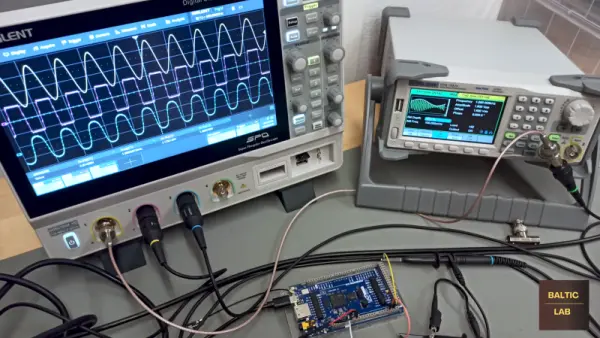
Now, there are a lot of different techniques for modifying the signal from an electric guitar, but perhaps the simplest is the humble diode clipping circuit. It just uses an op-amp with antiparallel diodes either in series in the feedback loop or shunting the output to ground. The diodes clip the tops and bottoms off of the sine waves, turning them into something closer to a square wave, adding those extra harmonics that really fatten the sound. It’s a simple hack that’s easy to implement in hardware, enough so that distortion pedals galore are commercially available.
In the video below, [Sebastian] explains that this distortion is also pretty easy to reproduce algorithmically. He breaks down the math behind this, which is actually pretty approachable — a step function with a linear part, a quadratic section, and a hard-clipping function. He also derives a second, natural exponent step function from the Schockley diode equation that is less computationally demanding. To implement these models, [Sebastian] chose an Arduino GIGA R1 WiFi, using an ADC to digitize the guitar signal and devoting a DAC to each of the two algorithms. Each distortion effect has its own charms; we prefer the harsher step function over the exponential algorithm, but different strokes.
Kudos to [Sebastian] for this easy-to-understand treatment of what could otherwise be a difficult subject to digest. We didn’t really expect that a guitar distortion pedal would lead down the rabbit hole to diode theory and digital signal processing, but we’re glad it did.
Source: GUITAR DISTORTION WITH DIODES IN CODE, NOT HARDWARE
- Can diode clipping distortion be simulated algorithmically?
Yes. The article explains simple mathematical models that reproduce diode clipping in code. - What mathematical functions are used to model diode clipping?
The article describes a piecewise step function with linear, quadratic, and hard-clipping sections, and an exponential function derived from the Schockley diode equation. - Which microcontroller was used to implement the distortion models?
An Arduino GIGA R1 WiFi was used for the implementation in the article. - How is the guitar signal handled in the digital implementation?
The guitar signal is digitized with an ADC on the Arduino, processed by the algorithms, and output through DACs. - Does each distortion algorithm use a separate DAC?
Yes. The article specifies a DAC devoted to each of the two algorithms. - Which algorithm produced harsher distortion?
The piecewise step function produced a harsher distortion compared to the exponential algorithm. - Is the exponential diode model computationally efficient?
Yes. The Schockley-derived exponential step function is noted as being less computationally demanding. - Does the article include a demonstration video?
Yes. The article references a video by Sebastian demonstrating the math and implementation.
