Summary of Experiment Objective: Utilizing Arduino Microcontroller for Switches, Sensors, LEDs, and Speaker Control
Summary: This lab teaches Arduino basics: blinking LEDs, reading digital and analog inputs, generating tones, and using a potentiometer and pushbutton to control outputs. Students upload and modify example sketches (Blink, DigitalReadSerial, AnalogReadSerial), measure voltages, convert ADC readings to volts, and create interactive sketches combining LEDs and a speaker.
Parts used in the Arduino Experiment:
- Two 1 kΩ resistors
- One 100 kΩ potentiometer
- One Arduino Uno
- One USB cable
- Debounced pushbutton (on proto-board)
- Proto-board with 5V and TTL/CMOS switches
- Speaker
- Oscilloscope (probe)
- Digital Multimeter (DMM)
I. Experiment Objective
The main goal of this experiment is to gain proficiency in using the Arduino microcontroller to observe switches and sensors and to trigger devices like LEDs or a speaker based on specific sensor output values.
II. Required Components List
This experiment will necessitate the following components:
• Two 1 kΩ resistors
• One 100 kΩ potentiometer
• One Arduino Uno
• One USB cable
III. Introduction
The Arduino is a versatile microcontroller board capable of reading switches and sensors while controlling various devices such as lights, speakers, motors, and more. Microcontrollers find applications in a wide range of devices like cars, cell phones, cameras, appliances, and printers. One of their significant uses is monitoring sensors and triggering output devices based on specific conditions. For instance, in a motion-controlled light, a microcontroller can turn on the light when a motion detector detects movement and turn it off after a set duration. Moreover, microcontrollers play a crucial role in monitoring sensors and controlling actuators, enabling functionalities in robots, quadcopters, and other devices.
IV. Pre-laboratory Assignment
1. What does the Arduino command “pinMode” do?
2. What does the Arduino command “digitalWrite” do?
3. What does the Arduino command “digitalRead” do?
4. What does the Arduino command “analogRead” do?
V. Experimental Procedure
Part 1: Arduino Set Up
In this section of the experiment, we will utilize a pre-existing sketch to make an LED blink on and off. The Arduino microcontroller is programmed through the use of Arduino software, a text editor that enables you to write programs known as sketches (refer to Figure 1).
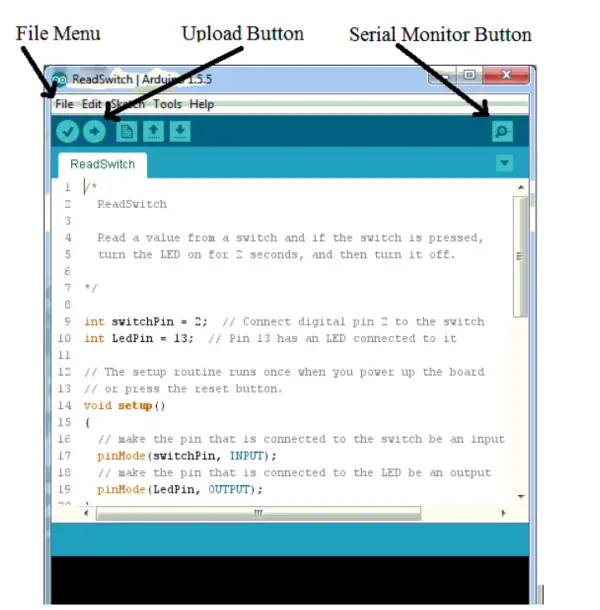
To begin, connect the Arduino board to your computer using the USB cable. Next, launch the Arduino software. Within the Arduino software, you will find various example sketches. Open the “Blink” example sketch by clicking on File, Examples, 01.Basics, Blink. This action will open the Blink sketch in a new Arduino window.
To set up the Arduino Uno board in the software, go to the “Tools” menu and select “Board.” From the options, choose “Arduino/Genuino Uno.” Additionally, click on “Tools,” then select “Port,” and choose the port labeled as “Arduino/Genuino Uno.” In case you do not see any ports labeled as such, try disconnecting and reconnecting the Arduino from the computer.
Press the “Upload” button (refer to Figure 1) to compile, upload, and execute the sketch. Once the process is finished, you should observe the LED near pin 13 blinking on for 1 second and then off for 1 second in a repetitive pattern. If you encounter an error like “Problem uploading to board,” go to the “Tools” menu, choose “Port,” and select a different port to resolve the issue.
Part 2: Blink Sketch
Now, let’s analyze the Blink sketch and customize it to blink in a pattern of your preference. The Arduino board is programmed using the C++ computer language, but the Arduino software provides various features that allow you to write sketches without needing an in-depth understanding of C++.
The introductory text in the Blink sketch serves as a comment. Comments are utilized to document the sketch for those who read or modify it, but they are disregarded by the Arduino software. There are two ways to denote text as a comment. If a line contains the characters “//”, anything after those characters is treated as a comment. Additionally, any text enclosed between “/*” and “*/” is considered a comment.
The “setup” function is responsible for initializing the sketch. It runs only once when the Arduino board is powered up for the first time or when the reset button is pressed.
The Arduino Uno is equipped with 14 general-purpose input/output (I/O) pins that can be configured as either inputs or outputs. Pin 13 on the Arduino board is connected to an LED, and the command “pinMode(LED_BUILTIN, OUTPUT)” configures pin 13 as an output because the value of LED_BUILTIN is set to 13 by the Arduino software. Any pin can be set as an output by replacing LED_BUILTIN with the corresponding pin number. Similarly, any pin can be set as an input by replacing OUTPUT with INPUT. It’s important to include a semicolon “;” after each command, and the commands inside a function are enclosed within curly brackets “{ }”.
Once the “setup” function is completed, the “loop” function is executed repeatedly until the Arduino is powered down or reset. In this sketch, the command “digitalWrite(LED_BUILTIN, HIGH)” is used to set Pin 13 to HIGH, resulting in the output of +5V and turning on the LED. By replacing LED_BUILTIN with the desired pin number, any pin can be set to HIGH. The “delay(1000)” command introduces a 1000 ms (or 1-second) pause. Following that, the “digitalWrite(LED_BUILTIN, LOW)” command sets Pin 13 to 0V, switching off the LED. After another 1000 ms pause, the “loop” function is called again, and the process repeats.
Part 3: Blink LEDs
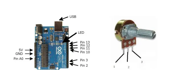
Create the circuit as depicted in Figure 2. Ensure that you connect the central connector (Pin 2) of the potentiometer to Arduino Pin A0, as illustrated in Figures 3 and 4. The Debounced Pushbutton is internally connected to ground, so there’s no need to make that connection manually. Be aware that the Arduino pin labeled as 5V is a power supply generated on the Arduino board specifically for this experiment. Therefore, refrain from connecting the bench supply or Proto-board supply to the Arduino.
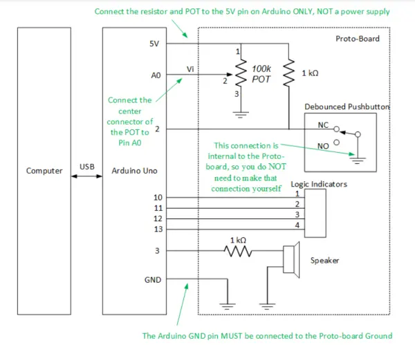
Ensure that the power to the Proto-board is switched on, as the Debounce Pushbutton circuit will not function without power. On the Proto-board, locate the Logic Indicator section and find the switch labeled 5V/+V. Set this switch to 5V. Additionally, there is another switch labeled TTL/CMOS; set this switch to TTL.
To test your circuit, use a Digital Multimeter (DMM) to measure the voltage at Arduino Pin 2. When the button is not pressed, it should read 0V, and when the button is pressed, it should read 5V. Similarly, the voltage at Arduino Pin A0 should vary between 0V and 5V as you adjust the knob on the potentiometer. It is essential to avoid connecting voltages greater than 5V or less than 0V to the Arduino input pins, as this could potentially damage the Arduino board.
Create a duplicate of the Blink sketch and save it in your P: drive by selecting File, Save As. Then proceed to customize the sketch to make the four Logic Indicator LEDs blink in a pattern of your preference. Remember to save your modified sketch to your P: drive.
Part 4: Read a Digital Input
In this section, we will explore an example sketch that deals with reading a digital input. This sketch can be adapted to monitor various sensors, including motion detectors, with digital outputs. To access the example sketch, click on File, Examples, 01.Basics, DigitalReadSerial.
Compile, upload, and run the sketch by selecting the Upload button. Next, click on the Serial Monitor button (see Figure 1). The Serial Monitor should display “0” when the button is not pressed and “1” when the button is pressed.
Now, let’s take a closer look at the DigitalReadSerial sketch. The line “int pushButton = 2” declares a variable named “pushButton” and assigns it the value 2. This variable is of type “int,” which means it can only hold integer values. Since this variable is defined outside of any function, it is considered global, allowing it to be used in various functions. The main purpose of this variable is to store the number of the input pin to which the pushbutton switch is connected.
Within the “setup” function, the line “Serial.begin(9600)” is used to initialize a serial connection with the computer, enabling data transfer at a rate of 9600 bits per second. This command is required for the sketch to print out any values to the computer. Additionally, the command “pinMode(pushButton, INPUT)” sets Pin 2 as an input. However, it’s worth noting that when the Arduino is powered up, it automatically sets the I/O pins to inputs, making this command optional in this specific case.
Within the “loop” function, the line “int buttonState = digitalRead(pushButton)” creates an integer variable called buttonState. In this case, since the variable is defined inside the “loop” function, it is considered private and can only be accessed by other commands within the same function.
The “digitalRead” function is then used to read the value from Pin 2 and store the result in the buttonState variable. When the voltage on the input pin is close to 5V, the “digitalRead” function returns the value 1, otherwise, it returns 0.
The line “Serial.println(buttonState)” is responsible for printing the value stored in the variable buttonState to the Serial Monitor. The “delay(1)” command introduces a 1 mS (millisecond) delay before the “loop” function repeats again. This continuous repetition of the “loop” function continues as long as the power is on, or until the Arduino is reset.
Make a duplicate of the DigitalReadSerial sketch and save it in your P: drive. To do this, click on File, and then choose Save As.
After the “digitalRead” line inside the “loop” function, add the following lines to modify the sketch’s behavior based on whether the switch is pressed or not.
if (buttonState == 0) // if switch is not pressed (note there are two equal signs)
{
digitalWrite(13, LOW); // turn LED off
}
else
{
digitalWrite(13, HIGH); // turn LED on
}
Test the changes you made in the sketch. When the switch is not pressed, the LED connected to Pin 13 should remain off, and when the switch is pressed, the LED should turn on.
Update the sketch to make the LEDs blink in two distinct patterns based on whether the switch is pressed or not. After making the modifications, save the updated sketch to your P: drive.
Part 5: Read an Analog Input
In this section, we will explore a sketch that reads an analog input voltage from a potentiometer. This sketch can also be adapted to monitor other sensors, like an RTD or photosensor, that provide analog output. To access the example sketch, click on File, Examples, 01.Basics, AnalogReadSerial.
Click on the Upload button and then open the Serial Monitor by clicking on its button (see Figure 1). As you turn the potentiometer knob, the voltage (Vi) in Figure 2 should vary between 0 and 5V, and the printed values in the Serial Monitor should also change accordingly. Observe the relationship between the voltage (Vi) and the values displayed in the Serial Monitor.
In the AnalogReadSerial sketch, the “setup” function initializes the serial connection to the computer at a rate of 9600 bits per second. In the “loop” function, the sketch uses the analogRead command to read the analog voltage from pin A0, converting the voltage to an integer. This integer value is stored in the variable sensorValue. The sketch then prints the value of sensorValue to the Serial Monitor, followed by a 1 mS delay.
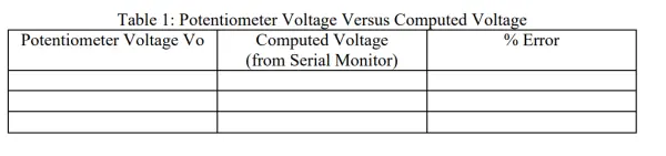
Save a copy of the AnalogReadSerial sketch in your P: drive by clicking on File, Save As. Then, modify the sketch to convert the value returned from the analogRead function to volts and print out the value in volts. To store the value in volts, you will need an additional variable capable of holding floating-point numbers, so use type “float” instead of “int.” Additionally, when computing the voltage, instruct the Arduino to use floating-point arithmetic by using constants with decimal points, such as 5.0 and 1023.0, instead of 5 and 1023. Run your sketch and record both the voltage Vi and the voltage computed by your program (see Table 1). Finally, calculate the percent error. Save your modified sketch to your P: drive.
Part 6: Making Tones
In this part of the experiment, we will create a new sketch to generate tones with a speaker. To begin, click on File, then New in the Arduino software. Next, type or paste the following sketch into the Arduino software editor.
/*
* Generate Tones
*/
int speakerPin = 3; // pin connected to the speaker
void setup()
{
// put your setup code here, to run once:
pinMode(speakerPin, OUTPUT); // set speakerPin to output
}
void loop()
{
// put your main code here, to run repeatedly:
int i; // loop counter
int frequency = 500; // frequency in Hz
int duration = 250; // duration in mS
int shortDelay = 500; // short delay time in mS
for (i = 0; i < 3; i++)
{
// generate tone
tone(speakerPin, frequency, duration);
delay(shortDelay); // short delay
}
delay(5000); // long delay
}
Execute the sketch. If the tones produced by the speaker are too faint, you can replace the 1 kΩ resistor that is in series with the speaker with a 150 Ω resistor. However, it is crucial not to reduce the resistance below 150 Ω, as doing so may harm the Arduino.
The tone function takes three arguments: the first argument is the pin number connected to the speaker, the second argument is the frequency of the tone in Hertz (Hz), and the third argument is the duration of the tone in milliseconds (mS).
The “for” command, also known as a for loop, repeats the tone and delay functions three times. The for command consists of three statements inside parentheses. The first statement “i = 0” is executed only once at the beginning of the loop, serving as the initialization of the loop counter. The second statement “i < 3” is a test, and if it evaluates to true, the enclosed statements are executed. After that, the third statement “i++” increments the loop counter by 1 in each iteration. This process continues until the test fails, and then the sketch proceeds to the commands following the loop.
Hence, the “for” command can be interpreted as a condensed version of the following commands:
i = 0; // initialize counter variable (this command is executed only once)
i < 3; // this test is true, so do the loop commands
tone(speakerPin, frequency, duration); // generate tone
delay(delayTime); // delay
i++; // increment loop counter, so now i equals 1
i < 3; // this test is true, so do the loop commands
tone(speakerPin, frequency, duration); // generate tone
delay(delayTime); // delay
i++; // increment loop counter, so now i equals 2
i < 3; // this test is true, so do the loop commands
tone(speakerPin, frequency, duration); // generate tone
delay(delayTime); // delay
i++; // increment loop counter, so now i equals 3
i < 3; // this test is now false, so skip down to the commands after the loop
Connect the oscilloscope probe to Arduino Pin 3 and measure the period of the tones produced by the speaker. Draw a sketch of the oscilloscope display, and indicate the period, maximum voltage, and minimum voltage on the sketch. Next, calculate the fundamental frequency of the tone and determine the percent error by comparing it to the frequency specified in the “tone” command.
Revise the sketch to produce tones according to your preference. Once you make the desired changes, save the modified sketch.
Part 7: Explore
Create a sketch to monitor the input from a switch, potentiometer, or sensor, and utilize that input to control the behavior of LEDs and/or the speaker in some manner.
VI. Conclusion
Throughout this lab, I have gained valuable knowledge about the Arduino microcontroller. An Arduino is a versatile microcontroller board that can be programmed to interact with switches, sensors, and various devices like LEDs and speakers. It serves as the brain of numerous electronic projects and finds applications in a wide range of tasks, such as home automation, robotics, sensor monitoring, and prototyping. In terms of analog voltage representation, the Arduino converts the analog signal from sensors or potentiometers into discrete digital values using its built-in analog-to-digital converter (ADC). This conversion process helps the Arduino process and manipulate analog data, making it a valuable tool for projects that involve continuous and variable signals.
Checkpoint 2:
Show your conclusion and demonstrate your sketch from Part 7 to the instructor.
- How do you make the onboard LED blink?
Upload the Blink example from File > Examples > 01.Basics > Blink and press Upload; LED on pin 13 will blink using digitalWrite and delay commands. - How can you read a pushbutton state?
Use the DigitalReadSerial example which sets pinMode for the button, uses digitalRead to get 0 or 1, and prints the value to the Serial Monitor. - How do you measure the potentiometer voltage?
Connect the potentiometer center to A0, then use AnalogReadSerial and observe values change in the Serial Monitor as you turn the knob; measure with a DMM between 0V and 5V. - What does analogRead return and how do you convert it to volts?
analogRead returns an integer 0–1023; convert to volts using floating-point arithmetic with 5.0 and 1023.0 to compute Vi. - Can you make a speaker produce tones from Arduino?
Yes; use tone(speakerPin, frequency, duration) in a sketch and set the speaker pin as OUTPUT; optionally change series resistor to 150 Ω if tones are faint but not below 150 Ω. - How do you change LED behavior based on a switch?
After digitalRead, use an if statement checking buttonState to digitalWrite pin 13 HIGH or LOW, and create different blink patterns for each state. - What must you avoid when connecting voltages to Arduino pins?
Do not connect voltages greater than 5V or less than 0V to Arduino input pins to prevent damage. - How do you save modified example sketches?
In the Arduino IDE choose File > Save As and save the duplicated/modified sketch to your P: drive.