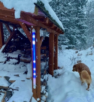
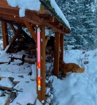
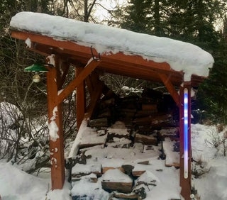
The days got shorter here in Alaska until it felt like the murky light was only a short interruption of a long sleep so I built a clock to display the seasonal diminishment (and expansion) of time. It also displays when it snows and how the tide is doing out there in the inky ice-choked sea. The neat display is another variation on wrangling the power of programmable LED’s to make them suitable for human eye consumption. In this case I am using a hemicircle of aluminum to reflect a moving mini tableaux that is a perfect accompaniment for the FASTLED framework of palettes.
The minimal hardware of a ESP32 jumps onto to your WIFI and gets information from both the NOAA website for tides and time information and also joins the Open Weather Map API for advice about the snow conditions. The device also displays an animated graphic of the current temperature that’s easily read from a distance and can be built into really any size device that you want. The end of days animation is a growing dark blue shadow that moves over a rainbow mapped to the limited daylight that it calculates every hour. The slow triumph of the rainbow over the shadow has just starting last week! The tidal animations show a murky moving blue sea underlaying a moving sky palette that changes depending on the time of day. Anyway, its something for you and your cat to look at for the next couple months.
Step 1: Gather Your Materials
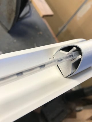
This project is easy to build with minimal materials but provides big impact for its size and animations. There is no correct size for the projection surface. Where before I utilized a closed tube with a hanging section of LEDs mounted on a rigid strip this new design is made possible by the availability of side mount led strip that can now be suspended by its own silicon shell from the ends of the tube section. The tube section itself can be made out of any material…plastic from the big box plumbing store but I built mine from aluminum for the look.
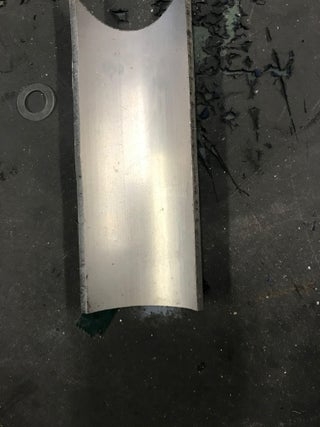
1. Section of 60 inch aluminum speed rail tube (ID 2″) cut with a saber saw into a 2 inch wide section. With testing, this reflective curvature from a suspension distance of about two inches, enabled the best graphics.
2. One-meter of Adafruit NeoPixel LED Side Light Strip – Black 60 LED $18
3. D1 mini ESP32 ESP-32 WiFi+Bluetooth
4. Waterproof DC Power Cable Set – 5.5/2.1mm
5. Power block 4A 5V–$10
6. LuckIn 20-Pack 1/2 x 1 Inch Stainless Steel Standoff Screws, Mounting Glass Hardware Sign $2
Step 2: Build It
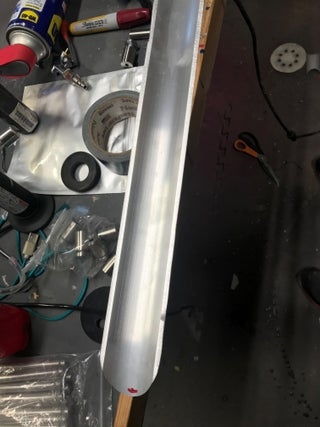
The tube section is easily cut with a metal saber saw blade after carefully outlining its shape on the speed tube. The cut may be fairly ragged and uneven but some moderate sanding with a table top sanding belt and a hand sander will bring it into true rather easily. The edge should be sanded until it has a flat profile and won’t cut your hand when handling it. The mounts at the top and bottom are for the stainless support posts from amazon and you can adjust their position and size depending on how large the mounting holes are and the length of your LED strip. The other side of the mounts that connect your instrument to the wall are made of excess curved sections of aluminum tube –the curve allows bolting the mounts into the curve that keeps it off of the wall. The surface treatment of the outside of the aluminum can be done with either fine wet dry sandpaper or can be sandblasted for delicate flat natural surface that can be painted with flat poly. The inside reflective surface has to be painted with a flat white paint with multiple coats to give it projective surface.
Step 3: 3D Print It
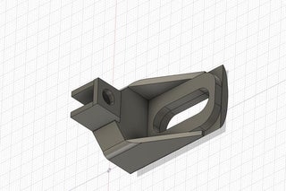
The 3D parts are all designed on Fusion 360. They form the support structure for the silicon sleeve and hold it in a taught vertical position. The slot on the bottom of the top and bottom holders accommodate the screw mounts for the stainless standoff supports. The separate bottom curved pieces enable the support structures to fit well onto the curved projection wing. Two connector structures are printed without support in PLA. Two covers and two curved underpieces are also printed. The case for the computer and power stud are also printed without support in PLA. The case has a screw cover that can be made more water resistant with an application of silicon grease.
Step 4: Wire It
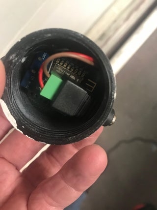
The wiring for this project is very easy. Attach the power plug to the +5 V and ground on the ESP32. The data line from the LED’s is connected to 17. The power and ground from the LED’s are also connected to the power plug. It is best to connect a large capacitor between ground and power in these Neopixel LED set ups and connect a small resistor to the data control line. Dabs of hot glue are also a good idea to stabilize the wiring from the ESP32. Hot glue the power stud into its matching hole on the case.
Step 5: Program It
Programming this relied on a variety of sources. The request for information to NOAA was done with the ESP32 Get request well documented in this project: https://www.instructables.com/Tide-and-Weather-Cl…You rely on a certificate included in the code for getting onto the site and taking down the current tide info–I use the period before and just peg the next tide for 6 hours later. The current time is taken off the header like in the example and is used in driving the color palettes of the sky in the tide display. A dark palette is used for the night and early morning and midday and late afternoon are all varied. The OpenWeatherMap api is then used to look for snow in the forecast. It also collects the sunup and sundown information(Unix Time) to calculate the total length of the day for display. It also collects the current temp for display. The API and its use is readily available information on the web. You must adapt it for the city that you live in. The functions in the program are used to graph out either the temp drop or the snowflake drop and rely on equations for objects falling and a variety of gravity constants to vary the falling rate for the flakes. The countable digits of the temp fall for the first number and then for the second–each in its own color. The tide level will vary with a map statement that adjusts the upward/downward movement of the randomly pulsing blue “seascape” palette. A red dot either at the top or bottom signifies which direction the tide is going. The bottom of the program consists of the various FASTLED palettes that are used in the display. These are input as an array and used in a variety of ways in the program. You can change out these arrays as you want with a variety of others from this website: http://soliton.vm.bytemark.co.uk/pub/cpt-city/view…Using the palette knife in the example is pretty easy to copy the selected color palette and input it into the program. Of most important note, upload the most recent version of the ESP32 boards (go to the GitHub site to get 1.0.5-rc4) to the Arduino IDE as earlier versions would not boot well on initialization and failed after a number of cycles. The current version has been running without complaint for a month.
Step 6: Build It
Construction is straight forward with attachment of the Silicon LED strip into the printed plastic holders — tying the wires in a knot secure their position for tightening them with the mounting screw. Small holes are drilled adjacent to the bottom holder to allow the wires to exit to the computer box. I soldered these to a clip connector so it was easy to remove and reattach the computer for easy access. You can mount the wall attachments first and then attach the rest of the fixture. The covers are finally hot glued over the end holders.
You can also easily build this unit out of a plastic plumbing tube of variable dimensions too. The most important thing is the relative projective placement of the suspended LED line to the inside concave lining of the tube. Too close and the reflective exposure is limited and too far away and most of the light overflow will go to the back wall. A more fully enclosed projective surface will also look different. You can make this clock in really any size that the pipe is available in and just connect sections of the LED line together.
Step 7: Using It
Put it up where the Wifi shines and plug it in. The unit is relatively water-resistant and can be used outdoors. The software has to be modified to include your own key to OpenWeatherMap which is easily done with sign up. The call-in is modified for your current city and so is the call to the NOAA site map for the current tide table where you live. Put in your current WiFi and password and it should light up. The fastLED functions for EVERY_N_MINUTES may be modified to call up at a different rate but it is currently set for every 15 minutes. It has been a slow winter up here. Sometimes you just need a little bit of light to make things better.
Source: End of Days Clock