Authors:
Kelly Bodeman – [email protected]
Jack Whelan – [email protected]
(For more questions contact us at our emails above)
Here is a link of a youtube video of our project: Connect Four Video
Acknowledgments
California Maritime Academy (Marine Engineering Technology)
Professor Chang-Siu (ET370 Electronics)
The Idea:
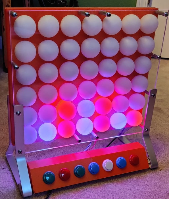
Connect Four is a two-player game typically consisting of a 7 x 6 board where players physically drop their chips into their desired slot. The goal of the game is to get four of your color in a row whether it be vertically, horizontally, or diagonally. Instead of physically dropping the chips into slots there are buttons that correspond to their nearest row. When the button is pressed the board will play an animation of a ball dropping. The color/player changes from blue and red every time a ball is dropped. The most challenging part of this project is detecting a win. The solution to this was to scan for a win every time a ball is placed, and at the location, it is placed. From that location, it scans in every possible direction (horizontal, vertical, and both diagonal directions). To keep things simple it only scans the nearest line, which also makes the win scan a little faster. Another thing to detect would be a tie, to detect a tie we could set a counter for how many plays there have been, and when that limit is reached it displays a tie.
Supplies
Below is the list of materials used for this project:
- Neo Pixel LEDs
- Arcade Buttons
- ping pong balls
- Arduino Uno
- Power Supply (Arduino) (9V 2.5A)
- Wires
- circuit boards
- breadboard
- PLC 3D Printing Material
- Acrylic Sheets
- Various screws
- Aluminum bar for stand
Step 1: Project Functionality
Description:
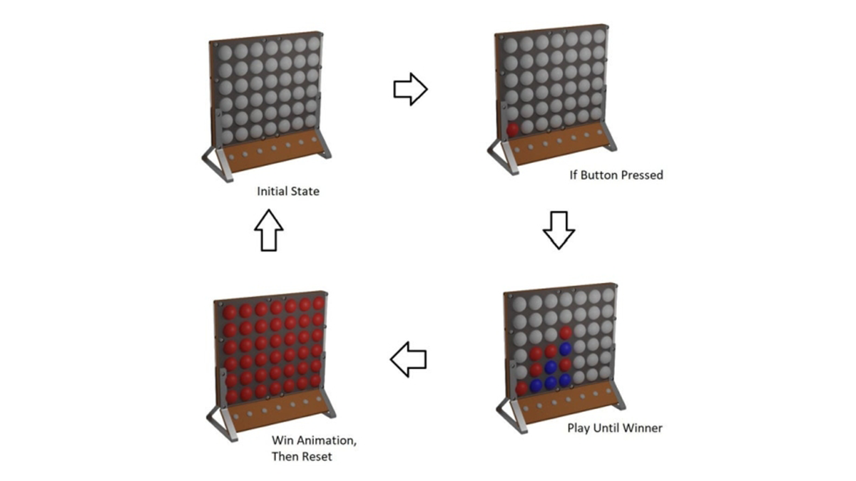
Above is the basic functionality of how the game will theoretically work. This game is designed to play identical to how one would play the real connect four. For example, if you plug the game in it won’t do anything until a button is pressed. Each button corresponds to the column it is below, which can be seen in the diagram. Once a button is pressed it will animate a puck dropping and it will place it in its corresponding place. However, if a column is completely full you will not be able to drop another puck. This continues until the program detects that any series of the lights have a four in a row it animates a win by progressively lighting up the whole board with whatever color won. If there is no winner and the board is completely full then you can reset the game. To restart the game at any time the side button can be pressed.
Step 2: Circuit Diagram
Description:
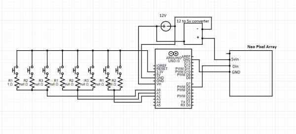
There are 8 buttons on this project. 7 of the buttons correspond to its nearest row. Then the 8th button is a reset button. Since we used an Arduino there were not enough input pins on the board to have each one have its own connection, so the solution to this was to use resistors at different values connected in parallel. This uses the concept of a voltage divider. Different voltages will be sensed for in the code and then show which resistor/button was pressed. The power source can be anything from 7-12 V. There is a voltage regulator that steps down the voltage to 5v to power the LED matrix, and also supplies the Arduino with whatever the incoming voltage is.
Power Consumption:
As for power consumption all of these components run at 5 V. Each neo-pixel has a max consumption of 60 mA, with 42 of these, and the Arduino itself has a max power usage of 50 mA. With all of this taken into account, we would need a 13 W power supply, at 5 V.
Step 3: Code Logic State Machine
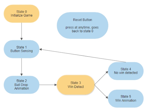
Above is the logic diagram which shows the basic concept of our code. When the game is plugged into the power source the game automatically starts which is in the “initialize game” state. This state also clears and sets the data. Then it goes straight to the “button sensing” state. The player colors are preset so all the player needs to do is press a button. Once a button is pressed it senses which column to drop the ball. Next, the code runs through the ball drop animation and then scans for a win. These steps repeat until it senses there are four of one color in a row, which would then go to the “win animation” state. Also at any time, the game can be reset with the reset button as shown above in the logic diagram.
There are still some flaws within our code. One of those is we need a tied state because it is possible to have no winner. Therefore, another state should be made since it is possible for that to happen. There are several other features that could be added but those will just be extra animations/states or fun improvements to this project.
The code is broken up into these four main states:
State 1, Button Sensing
State 2, Ball Drop Animation
State 3, Win Detect
State 4, Win Animation
Step 4: Code
Button Sensing:
  if ( voltage1 > 4.4 && voltage1 < 4.9 && buttonblock == 0 && overload[0] == 0) {
    Serial.println ("button 1");
    buttonstate[0] = 1;
    buttonblock = 1;
  }
      if (buttonstateprev1 == 0 && buttonstate[0] == 1) {
        State = 2;
        x = 0;
        break;
      }
As stated before the buttons use a voltage divider and then sense the voltage to know which button was pressed. We first found what voltage each button was sensing when pressed then but a range into the code so it would know whether the 1st or 2nd or 3rd button was pressed. The buttons are broken into 3 branches since we did not have enough variation in the voltages which so we broke them into separate input in the code which caused no issue.
Ball Drop Animation:
    case 2: //animation
      Serial.println("in State 2 (animation)");
      Serial.print("anistate = ");
      Serial.println(anistate);
      switch (anistate) {
        case 1: //checking for overload and adjusting if it sees anything
          if (y[x] <= 0) {
            y[x] = 0;
            Serial.print("row overload");
            overload[x] = 1;
            anistate = 2;
          }
          else {
            anistate = 2;
          }
          break;
The ball drop animation was pretty simple. All it does is check the hight of the active row and animates the ball until it reaches that height. After that is sets the new color, sets the height of the active row, and sends it to the next state. The actual animation part of this code just draws a pixel on the matrix, shows it, then deletes that drawn pixel and moves to the next one below and shows that. This repeats until it reaches the height of that row.
Win Detect:
    case 3: //win detect
      switch (winstate) {
        case 0: //setting led states
          Serial.println("winstate 0");
          scanX = 0;
          win = 0;
          scanY = y[x] + 1;
          winstate = 1;
          break;

        case 1: // horizontal scan
          if ( BoardMatrixState[scanX][scanY] == BoardMatrixState[x][Y]) {
            win++;
          }
          else {
            win = 0;
          }
          if (win >= 4 ) {
            Serial.println("someone won horizontal");
            State = 4; //win detected
            break;
          }
          if (scanX >= 6) {
            win = 0;
            scanY = 0;
            scanX = x;
            winstate = 2; //move to vertical scan
            break;
          }
          scanX++;
          break;
      break;
There are 4 win cases: horizontal, vertical, diagonal up/down. Each different win scenario has its own case. To make the scan easier we created a matrix of arrays to help sense the location of LEDs of where the ball was dropped. When looking at the code we designated the Blue = 1 & Red = 2.
Win Animation:
    case 4: //Win Animation
      // 1 is blue, 2 is red, 0 is off
      delay(2000);
      if (BoardMatrixState[x][Y] == 2) {
        colorWipe(strip.Color(255,   0,   0), 100);
      }
      else {
        colorWipe(strip.Color(0,   0,   255), 100);
      }
      State = 5;
      break;
    case 5:
      if (buttonstateprev1 == 0 && buttonstate[7] == 1) {
        digitalWrite(Reset, LOW); //resets arduino

      }
      break;
The win animation starts after a win is detected. The code runs through a simple color swipe which displays the winner color across the board. After this, you can reset the game but pressing the reset button on the side of the board.
Step 5: CAD Drawing
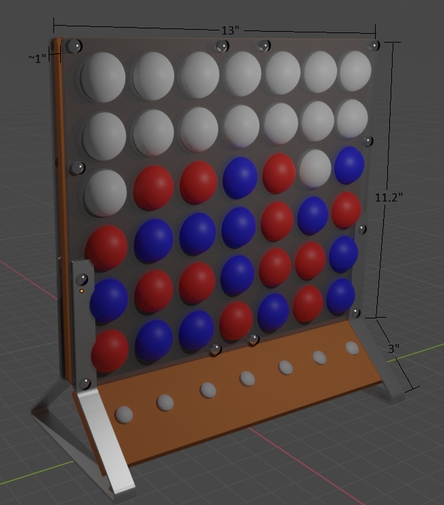
First off we started making a 3D CAD drawing of the whole game, theoretically, we wanted the final product to be similar. We wanted to keep the same design as a normal connect four board but we wanted to make it a little different which is why we used the ping pong balls to cover the LED, to make the game pop out more. Since we could not buy a connect four board that would be big for our design, we custom made the board by 3D printing it into 4 parts. Above are the 2 designs we thought would be ideal for the game, after some debate we decided to use the left version.
Using CAD was very important to help visualize how the project would work. Any complex parts were designed using Autodesk Inventor and then 3D printed. Any renderings depicted were made using Blender
Source: Electronic Connect Four (arduino)