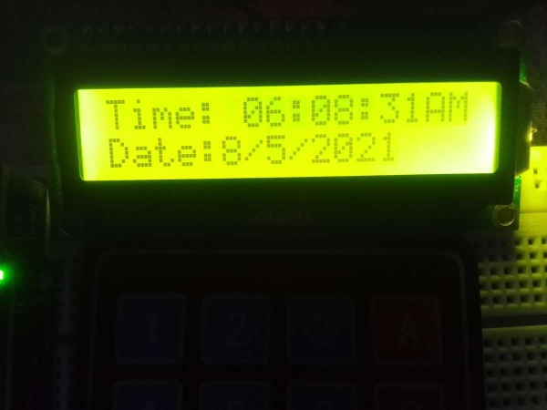
Summary of Digital Clock using Arduino UNO Without RTC module
This article details a low-cost Digital Clock project built using an Arduino UNO without an external RTC module. The system utilizes a 4x4 keypad for manual time and date input, displaying the output on a 16x2 LCD screen via an I2C interface. The design emphasizes creativity and productivity by eliminating expensive hardware while offering battery power and visibility in dark environments.
Parts used in the Digital Clock:
- Arduino UNO
- 4x4 Keypad
- 16x2 LCD Display Module
- Arduino UNO v5.0 Shield
- I2C Module with PCF8574 chip
An interesting project of making a Digital Clock using Arduino UNO without the help of RTC Module.
Description
AIM
To build a Digital Clock at Low Cost (Without using any External RTC Module)
ject, I have used LCD 16X2 Display , an Arduino UNO , a 4×4 keypad and Arduino UNO v5.0 Shield to proceed with. The main purpose of the project is about creativity and Productivity. I was trying to look from different sources on Internet but could not get any help. The project is effective and interesting and done at a very low cost . And , its true this project cannot be found on Internet.
MODULES
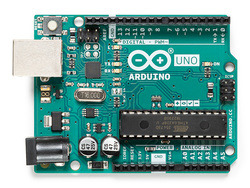
- Arduino UNO
The Arduino Uno is a microcontroller board based on the ATmega328. It has 20 digital input/output pins (of which 6 can be used as PWM outputs and 6 can be used as analog inputs), a 16 MHz resonator, a USB connection, a power jack, an in-circuit system programming (ICSP) header, and a reset button. It contains everything needed to support the microcontroller; simply connect it to a computer with a USB cable or power it with a AC to DC adapter or battery to get started. Programs can be loaded on to it from the easy-to-use Arduino computer program. The Arduino has an extensive support community, which makes it a very easy way to get started working with embedded electronics. The R3 is the third, and latest, revision of the Arduino Uno.
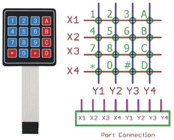
- 4×4 Keypad
A matrix keypad is a small compact input device that accepts user inputs and processed by Microcontrollers. You might have seen this in most commonly used devices like Calculators, Digital locks, Gas pumps and DIY projects. It comes in different types, one of them is membrane keypads, it is thinner in size and you can paste it on top of your creative projects.
If we have to connect 16 buttons to the microcontroller, then each button takes 1 GPIO pin. But if we use the matrix keypad we just need 8 pins only. Initially, all rows are set to (LOW) and all Columns are set to (HIGH). When a key press occurs the column pin will get contacted to the row pin and makes the entire column state to low. To identify the exact pin at the column, we need to scan each row by sending 1 (HIGH) and read the state at Column pins. The column which changes the state from 0(LOW) to 1(HIGH) then that is the location of the pressed key (Passes the HIGH signal from Row to Column pin). Let’s see this in detail with an example
In the idle state, the row and column will be like this,
Row R1 R2 R3 R4 – 0000
Column C1 C2 C3 C4– 1111
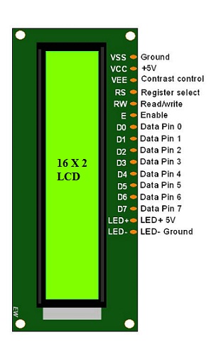
- 16×2 LCD Display Module
16×2 LCD is one kind of electronic device used to display the message and data. The term LCD full form is Liquid Crystal Display. The display has 16 Columns and 2 Rows. it can be displayed 32 characters in total and each character will be made of 5×8 Pixel Dots. These displays are mainly based on multi-segment light-emitting diodes. The 16×2 LCD is widely used. These LCD modules are low cost, and programmer-friendly, therefore, is used in various DIY circuits, devices, and embedded projects.
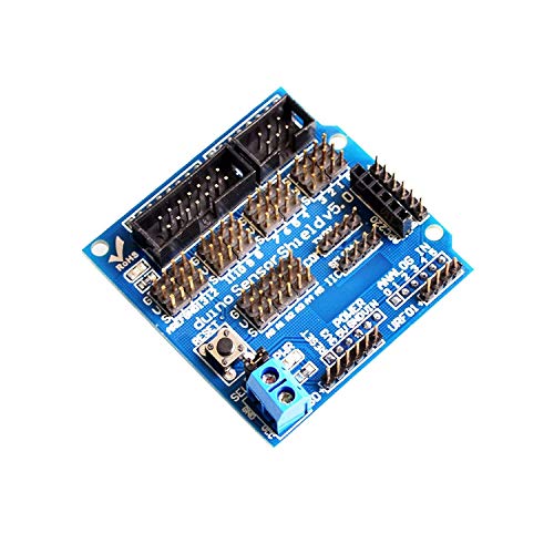
- Arduino UNO sensor Shield v5.0
Arduino shields are the boards, which are plugged over the Arduino board to expand its functionalities. There are different varieties of shields used for various tasks, such as Arduino motor shields, Arduino communication shields, etc.
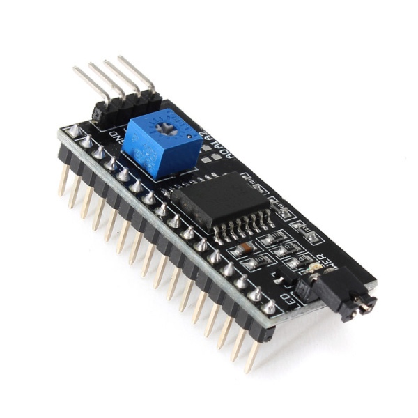
- I2C Module
I2C Module has a inbuilt PCF8574 I2C chip that converts I2C serial data to parallel data for the LCD display. These modules are currently supplied with a default I2C address of either 0x27 or 0x3F. To determine which version you have check the black I2C adaptor board on the underside of the module. If there a 3 sets of pads labelled A0, A1, & A2 then the default address will be 0x3F. If there are no pads the default address will be 0x27.
The module has a contrast adjustment pot on the underside of the display. This may require adjusting for the screen to display text correctly.
Features:-
- Operating Voltage: 5V
- Backlight and Contrast is adjusted by potentiometer
- Serial I2C control of LCD display using PCF8574
- Come with 2 IIC interface, which can be connected by Dupont Line or IIC dedicated cable
- Compatible for 16×2 LCD
- This is another great IIC/I2C/TWI/SPI Serial Interface
- With this I2C interface module, you will be able to realize data display via only 2 wires.
DATASHEETS
- https://www.farnell.com/datasheets/1682209.pdf
- https://www.futurlec.com/LED/LCD16X2BLa.shtml
- https://cdn.sparkfun.com/assets/f/f/a/5/0/DS-16038.pdf
- http://www.mantech.co.za/datasheets/products/lcd2004-i2c.pdf
ADVANTAGES
• It is effective and has Low-cost option.
• It can be used in dark environments and due to its lighting configuration
• It is mainly powered by battery (no external power supply needed)
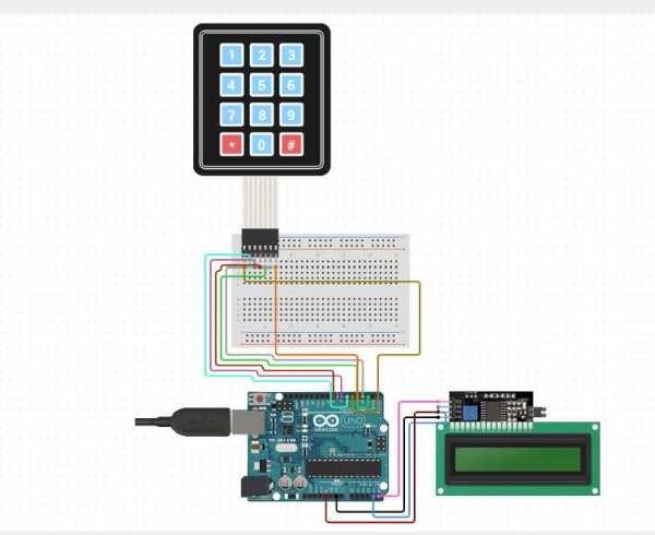
SCHEMATIC DIAGRAM
PROJECT DESCRIPTION
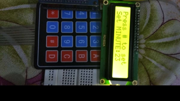
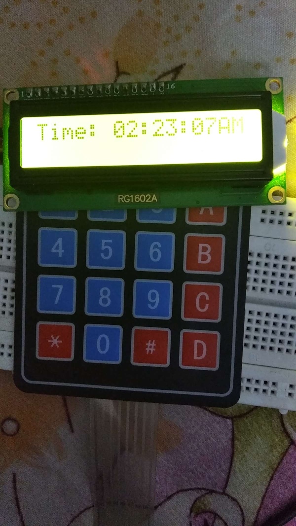
In this project we have the above mentioned components and the working is quite east to understand .The input will be taken from the user through the matrix keypad. At first we have to give The Hour and then minutes. Then we have to insert Date and month and year format. The AM and PM format will be automatically set on the basis of 24 hours configuration.
I2C module is connected with Arduino sensor shield through TX(0) and RX(1) pin with SDA and SCL pins. Here, different I2c Library functions are used to make project understand a little bit easier.
The matrix keypad has 8 pins connected with Arduino UNO sensor shield.
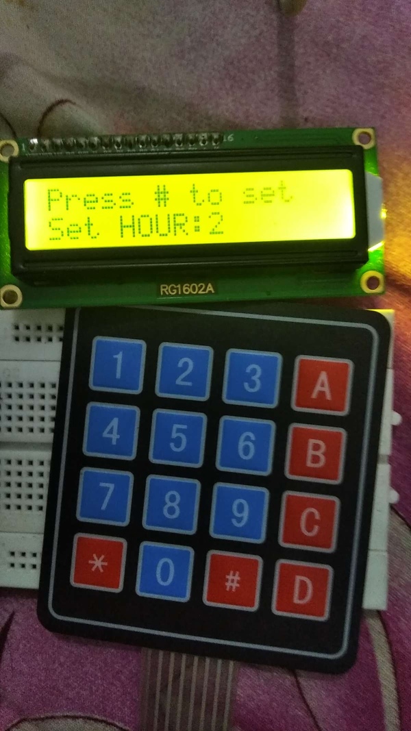
After entering the date ,month, hour, minute and second the data will be displayed on the LCD display.
Here are some images that describe the working in an easy way:-
Source: Digital Clock using Arduino UNO Without RTC module
- How does the matrix keypad reduce pin usage?
A matrix keypad requires only 8 pins instead of 16 GPIO pins because it uses rows and columns to identify pressed keys. - Can this clock operate without an external RTC module?
Yes, the project is specifically designed to function as a digital clock without using any external RTC module. - What is the default I2C address for the module?
The default I2C address is either 0x27 or 0x3F, depending on whether the board has A0, A1, and A2 pads. - Does the display support operation in dark environments?
Yes, the clock can be used in dark environments due to its specific lighting configuration. - How is the AM and PM format determined?
The AM and PM format is automatically set based on the 24-hour configuration entered by the user. - What type of power supply is recommended?
The project is mainly powered by a battery, meaning no external power supply is needed. - How many characters can the LCD display at once?
The 16x2 LCD can display a total of 32 characters across 16 columns and 2 rows. - Which pins connect the I2C module to the shield?
The I2C module connects to the Arduino sensor shield through TX(0) and RX(1) pins along with SDA and SCL pins.