In optical microscopes, there is a fundamental trade-off between field-of-view and resolution: the finer the detail, the smaller the region imaged by the microscope. One way to overcome this limitation is to translate the sample and acquire images over a larger field-of-view. The basic idea is to stitch together many high resolution images to form a large FOV. In these images, you get to see both the full sample, as well as fine detail in any portion of the sample. The result is an image consisting of about a billion pixels, much larger in comparison to the pictures taken by a dSLR or smart phone, which typically have around 10 to 50 million pixels. Check out these gigapixel landscapes for an impressive demonstration of the massive amount of information in these images.
In this instructable, I will go over how to build a microscope capable of imaging a 90mm x 60mm field-of-view with pixels corresponding to 2μm at the sample (although, I think the resolution is probably closer to 15μm). The system uses camera lenses, but the same concept can be applied using microscope objectives to get even finer resolution.
I uploaded the gigapixel images I acquired with the microscope on EasyZoom:
1970 National Geographic magazine image
Crochet tablecloth my wife made
Other resources:
Optical microscopy tutorials: https://www.microscopyu.com/
Optical resolution: https://en.wikipedia.org/wiki/Diffraction-limited_…
In addition to image stitching, recent progress in computational imaging makes gigapixel microscopy possible without even moving the sample!
Step 1: Supply List
Materials:
1. Nikon dSLR (I used my Nikon D5000)
2. 28mm focal length lens with 52mm threading
3. 80mm focal length lens with 58mm threading
4. 52mm to 58mm reverse coupler
5. Tripod
6. Seven sheets of 3mm thick plywood
7. Arduino Nano
8. Two H-bridge L9110 https://www.amazon.com/gp/product/B00NN6EB3U/ref=o…
9. Two IR emitters
10. Two IR receivers
11. Push button
12. Two 2.2kOhm resistors
13. Two 150Ohm resistors
14. One 1kOhm resistor
15. Remote release for Nikon camera https://www.amazon.com/gp/product/B00MCA191K/ref=o…
16. Black poster board
17. Hardware kit: https://www.amazon.com/gp/product/B06XQMBDMX/ref=o…
18. Two stepper motors (I used Nema 17 Bipolar step motor 3.5V 1A)
19. Two 2mm lead screws
20. Four pillow blocks
21. Two lead screw nuts
22. Two bearing slide bushing and 200mm linear shafts: https://www.amazon.com/gp/product/B01KL7I65W/ref=p…
23. 5V power supply: https://www.amazon.com/gp/product/B01M0KLECZ/ref=o…
24. Wire wrap wire
Tools:
1. Laser cutter
2. 3D printer
3. Allen wrenches
4. Wire cutters
5. Wire wrap tool
Step 2: System Overview
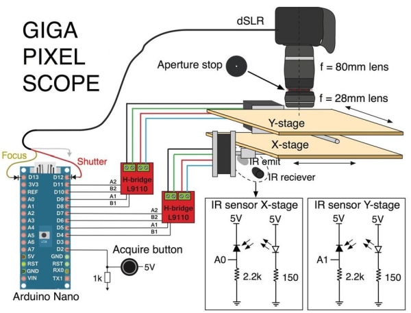
To translate the sample, two stepper motors aligned in orthogonal directions move a stage in the x and y direction. The motors are controlled using two H-bridges and an Arduino. An IR sensor positioned at the base of the stepper motor is used to zero the stages so they don’t run into either end of the blocks. A digital microscope is positioned above the XY stage.
Once the sample is positioned and the stage is centered, you push a button to begin the acquisition. The motors move the stage to the bottom left corner and the camera is triggered. The motors then translate the sample in small steps, as the camera takes a photo at each position.
After all the images are taken, the images are then stitched together to form a gigapixel image.
Step 3: Microscope Assembly
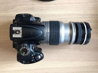
I made a low magnification microscope with a dSLR (Nikon 5000), a Nikon 28mm f/2.8 lens, and a Nikon 28-80mm zoom lens. The zoom lens was set for focal length equal to 80mm. The set of the two lenses acts like a microscope tube lens and objective lens. The total magnification is the ratio of the focal lengths, around 3X. These lenses are really not designed for this configuration, so to make the light propagate like a microscope, you have to position an aperture stop between the two lenses.
First, mount the longer focal length lens to the camera. Cut a circle out of black poster board that has a diameter roughly the size of the front surface of the lens. Then cut a small circle in the middle (I chose about 3mm diameter). The size of the circle will determine the amount of light that enters the system, also called the numerical aperture (NA). The NA determines the lateral resolution of the system for well designed microscopes. So why not use a high NA for this setup? Well, there are two major reasons. Firstly, as the NA increases, the optical aberrations of the system become more prominent and will limit the resolution of the system. In an unconventional setup like this, this will likely be the case, so increasing the NA eventually will no longer help improve the resolution. Secondly, the depth of field also depends on NA. The higher the NA, the shallower the depth of field. This makes it difficult to get objects that aren’t flat all into focus. If the NA gets too high, then you will be limited to imaging microscope slides, which have thin samples.
The positioning of the aperture stop between the two lenses makes the system roughly telecentric. That means the magnification of the system is independent of the object distance. This becomes important for stitching images together. If the object has varying depth, then the view from two different positions will have shifted perspective (like human vision). Stitching images together that are not from a telecentric imaging system is challenging, especially with such high magnification.
Use the 58mm to 52mm lens reverse coupler to attach the 28mm lens to the 80mm lens with the aperture positioned in the middle.
Step 4: XY Stage Design
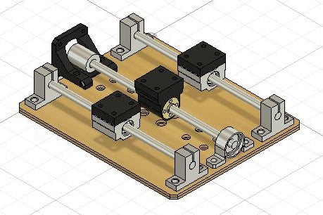
I designed the stage using Fusion 360. For each scan direction, there are four parts that need to be 3D printed: mounter mount, two slide unit extenders, and a lead screw mount. The base and platforms of the XY stage are laser cut from 3mm thick plywood. The base holds the X-direction motor and sliders, the X-platform holds the Y-direction motor and sliders, and the Y-platform holds the sample. The base consists of 3 sheets and the two platforms consist of 2 sheets. The files for laser cutting and 3D printing are provided in this step. After cutting and printing these parts you are ready for the next steps.
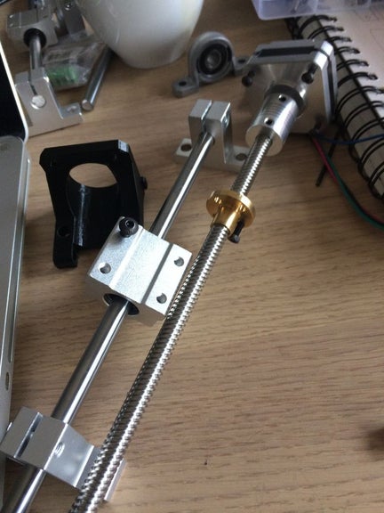
Step 5: Motor Mount Assembly
Using a wire-wrap tool, wrap wire around the leads of two IR emitters and two IR receivers. Color code the wires so you know which end is which. Then cut the leads off the diodes, so just the wire wrap wires run from then. Slide the wires through the guides in the motor mount and then push the diodes into place. The wires are directed so they are not visible until they exit the rear of the unit. These wires can be joined with the motor wires. Now mount the stepper motor using four M3 bolts. Repeat this step for the second motor.
Step 6: Stage Assembly
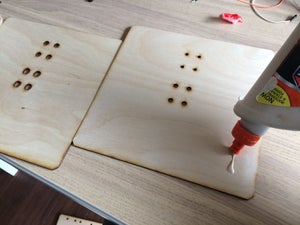
Glue together the Base 1 and Base 2 cuts, one of them with hexagonal openings for the M3 nuts. Once the glue has dried, hammer the M3 nuts into position. The nuts will not rotate when pressed into the board, so you will be able to screw in the bolts later. Now glue the third base sheet (Base 3) to cover the nuts.
Now it is time to assemble the lead-nut mount. Clear out any extra filament from the mount and then push four M3 nuts into position. They are a tight fit, so make sure you clear out the bolt and nut space with a small screw driver. Once the nuts are aligned, push the lead-nut into the mount and attach it with 4 M3 bolts.
Attach the pillow blocks, slider mounts, and motor mount for the X-direction linear translator onto the base. Put the lead nut assembly onto the lead screw and then slide the lead screw into place. Use the coupler to connect the the motor to the lead screw. Place the slider units into the rods and then push the rods into the slider mounts. Finally, attach the slider mount extenders with M3 bolts.
The X1 and X2 plywood sheets are glued together in a similar way to the base. The same procedure is repeated for the Y-direction linear translator and the sample stage.
Source: Desktop Gigapixel Microscope