Summary of Dazzle Your Eyes with a Twinkling LED Symphony: Learn to Create Your Own LED Display
This article describes an Arduino Nano–based random LED flasher that controls twenty LEDs, lighting only one LED at a time chosen by a random number in the sketch. A potentiometer (VR1) adjusts the delay between activations. The design can be built on breadboard, stripboard, or PCB, with provided schematic, PCB layout, and component placement views for assembly and testing.
Parts used in the Random LED Flasher:
- Arduino Nano (ATmega328P)
- 20 LEDs
- Resistors for LEDs
- Potentiometer VR1
- Breadboard or stripboard or printed circuit board (PCB)
- Wires/jumper leads
- USB cable for programming/power (mini USB)
- Solder and soldering tools (for PCB assembly)
- Computer with Arduino IDE
This circuit demonstration showcases a random LED flasher controlling twenty lights. LED flashers and sequencers are commonly employed in decorative lighting applications to produce aesthetically pleasing color patterns.
Rather than steadfast illumination, these systems cycle LEDs on and off in either a predetermined sequence or at irregular intervals. The latter approach generates a more dynamic, unpredictable appearance.
At the heart of this demonstration is a microchip programmed to randomly vary the flashing rate of each individual LED. Without any set pattern or routine, the lights come on and off independently of one another.
This produces an ever-changing interplay of illuminated and darkened LEDs across the array. Such a random flasher circuit renders colorful visual interest well-suited for applications like holiday decor, mood lighting, and general aesthetic lighting effects.
Circuit and working
This circuit demonstration showcases a random LED flasher controlling twenty lights. LED flashers and sequencers are commonly employed in decorative lighting applications to produce aesthetically pleasing color patterns.
Rather than steadfast illumination, these systems cycle LEDs on and off in either a predetermined sequence or at irregular intervals. The latter approach generates a more dynamic, unpredictable appearance.
At the heart of this demonstration is a microchip programmed to randomly vary the flashing rate of each individual LED. Without any set pattern or routine, the lights come on and off independently of one another.
This produces an ever-changing interplay of illuminated and darkened LEDs across the array. Such a random flasher circuit renders colorful visual interest well-suited for applications like holiday decor, mood lighting, and general aesthetic lighting effects.

The Arduino programming ensures only a single LED lights up at any given moment. A random number is generated within the code corresponding to one of the input/output pins on the Arduino board.
This assigns which LED will illuminate based on its connection to that randomly selected I/O pin. The delay period between consecutive LED activations is adjustable using potentiometer VR1.
As each LED switches off, another is randomly chosen to switch on after the set delay. This results in the LEDs flashing sequentially in an unpredictable order, with one illuminating at a time.
The randomized LED flashing will repeat continuously in this fashion until power is removed from the circuit. VR1 allows tuning the speed of the flickering between fast and slow transitions from one lit LED to the next.
Together, the random number generation and delay timing produce the continually varying single-LED illumination that characterizes this demonstration of an Arduino-controlled random flasher circuit.
Arduino Nano
The Arduino Nano is a small yet capable microcontroller board based around the ATmega328P chip. While providing the same functionality as the Arduino Uno, it has a more compact footprint at just 43mm x 18mm in size.
It contains 14 digital input/output pins, six of which support pulse width modulation (PWM). There are also eight analog inputs and a 16MHz clock speed powered by the 32KB of onboard flash memory. Unlike the Uno, the Nano uses a mini USB connector instead of a standard socket. Power must also be supplied via the USB port rather than an external barrel jack.
The random LED flasher software is written as an Arduino sketch (Flasher.ino) using the Arduino programming language. To upload this code to the Nano, it must first be connected to a computer running the Arduino IDE. From within the IDE environment, the proper board is selected from the tools menu along with selecting the COM port. Then the flasher sketch can be compiled and loaded over the USB connection.
Once programmed, the compact yet capable Arduino Nano serves as the microcontroller driving the random flashing behavior of the LED array through digital output pins selected at random intervals.
Construction and testing
To assemble the circuit, LEDs 1 through 20 must be wired to corresponding digital pins on the Arduino Nano according to the schematic. A breadboard, stripboard, or printed circuit board (PCB) is necessary to facilitate connecting the LEDs and associated resistors to the microcontroller ports in an organized manner.
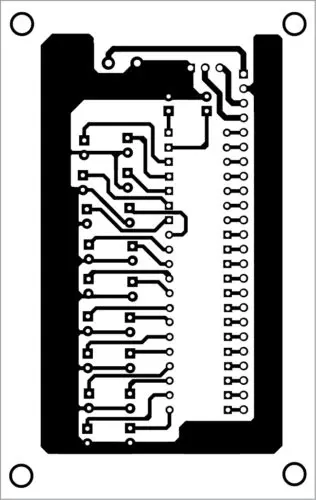
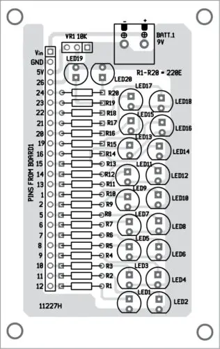
Figures 2 and 3 depict the circuit design in more detail. Figure 2 shows the PCB layout, illustrating how the circuit traces are routed on the board. Then Figure 3 provides the component placement view, specifying where each discrete part such as the LEDs and resistors should be soldered on the PCB.
Following these graphical designs carefully permits replication of the exact circuit configuration to programmatic specifications. The PCB option offers a compact, robust solution compared to breadboarding. But any arrangement allowing the LED-to-pin mappings shown in the schematic to be achieved is suitable for evaluating this random flasher demonstration circuit in action.
- What microcontroller is used in the project?
The Arduino Nano (ATmega328P) is used as the microcontroller. - How many LEDs does the circuit control?
The circuit controls twenty LEDs. - Does the circuit light multiple LEDs simultaneously?
No, the Arduino programming ensures only a single LED lights up at any given moment. - How is the next LED chosen?
The sketch generates a random number corresponding to one of the Arduino digital I/O pins to select the next LED. - Can the flashing speed be adjusted?
Yes, the delay between LED activations is adjustable using potentiometer VR1. - What board options can be used to assemble the circuit?
The circuit can be assembled on a breadboard, stripboard, or printed circuit board (PCB). - How is the code uploaded to the Arduino Nano?
Connect the Nano to a computer via the USB cable, select the correct board and COM port in the Arduino IDE, then compile and upload the Flasher.ino sketch. - Will the random flashing continue without intervention?
Yes, the randomized LED flashing repeats continuously until power is removed from the circuit.