Summary of Custom I2C Slave Sensor/device With Arduino
This article details creating a custom I2C slave device using an Arduino Nano to control an AC dimmer module, offloading interrupt handling from a master controller. The setup involves two Arduinos communicating via I2C: one acts as the master sending commands, while the other (slave) manages the dimmer's zero-crossing detection and PWM output. This architecture simplifies the main project by dedicating specific pins for critical AC control tasks.
Parts used in the Custom I2C Slave Sensor/device:
- Arduino Nano
- AC Dimmer Module
- Mini Breadboards
- Jumper Wires
In this Instructable, I’ll show you how I managed to create my own I2C controlled device that I can then connect to any microcontroller and interact with it over I2C.
In my case, I’m using it to control an AC dimmer module from a separate Arduino Nano and I then interact with it from another Arduino Nano. You can check the details for controlling the dimmer module in its own Instructable.
This post is sponsored by PCBWay. Get your custom PCBs, SMD stencils, or assembly services professionally done for cheap in less than 24 hours. PCBWay also offers sponsorships for students and hobbyists where you can get your projects built for free.
Supplies
Tools and materials used in the video:
- Arduino Nano – https://s.click.aliexpress.com/e/_Aey8wk
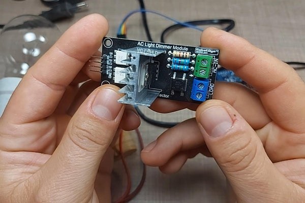
- AC Dimmer Module – https://s.click.aliexpress.com/e/_A2DIQ4
- Mini Breadboards – https://s.click.aliexpress.com/e/_A69aO4
- Jumper Wires – https://s.click.aliexpress.com/e/_AFkya8
Step 1: The Idea
I’m currently working on a bigger project where I need multiple interrupt pins for various sensors and inputs so I was faced with the issue that I ran out of pins.
The dimmer module that I’m using, needs an interrupt pin for the zero-crossing signal that it generates from the mains AC and it then controls the on time for the triac based on that signal. This is quite some work that the controller needs to do, so in order to lighten up the workload on the main controller, I had the idea to separate the AC control to a different Arduino and have the main controller interact with it via I2C.
This way, the main Arduino will only need to deal with the dimmer once to send out the output value and can do the rest of the monitoring in the meantime, while the second Arduino monitors and controls the fan.
Since this is a relatively simple device I originally intended to use an Attiny85 controller for the dimmer controller but I was unable to do so since the I2C pins on the Attiny85 are the same as with the only available interrupt pin.
I read online about a possible solution for using software I2C but I was unable to complete it. If you have any ideas or pointers on how I can achieve this, be sure to leave me a comment.
Instead, I used another Arduino Nano and that worked without issues since the Nano has the I2C lines on pins A4 and A5 while the interrupt is on pin 2.
Step 2: Wiring It Up
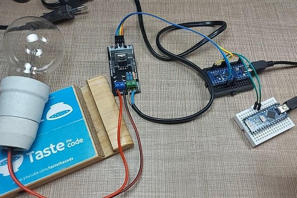
The connections to the AC dimmer module are really simple where besides VCC and GND we need to connect two more pins to the Arduino. In my case, I have the zero-crossing signal coming into pin 2 as this needs to be connected to an interrupt pin and the PWM pin of the module is connected to pin 5 on the Arduino.
The AC line is connected to the input terminal of the module while the light bulb is connected to the load terminal.
Since this is mains voltage, be extra careful with it as any mistakes can seriously injure or even kill you.
To connect the slave Arduino to the master, we need to connect the I2C lines of both Arduinos together. In the case of the Arduino Nano, the pins are A4 and A5 and they need to be connected on both boards together.
Step 3: Code
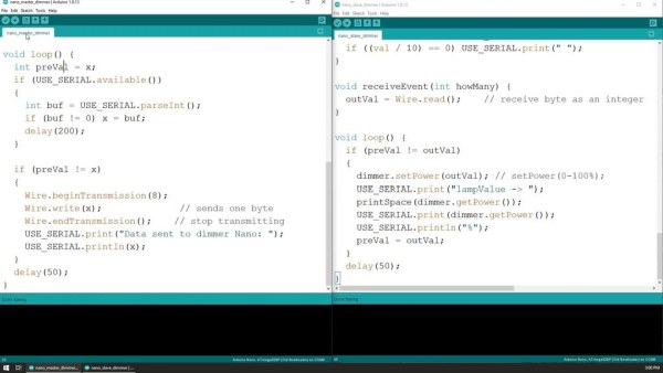
The code used on the two Arduino boards is attached to this Instructable.
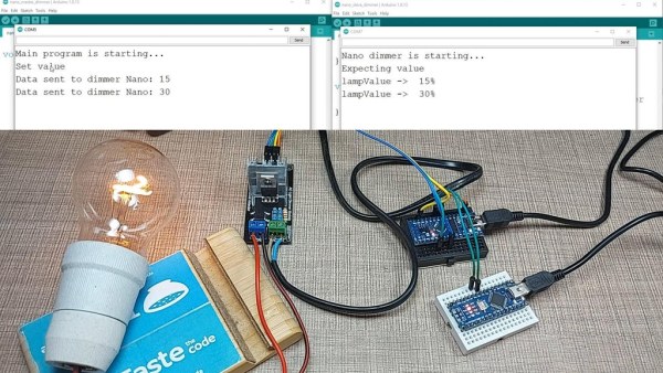
In a nutshell, the slave Arduino listens for incoming data on a specific I2C address and when a new value is received, it sends that value to the dimmer library to specify the intensity at which the load is on.
The sole purpose of the master Arduino is to wait for input from the serial monitor on the Arduino IDE and it then relays that information to the slave Arduino at the same address where it listens.
Step 4: Next Steps
The example should give you a clear understanding of how I2C slave mode works and from it, you can then go and build your own custom devices and sensors that can then be integrated with more complicated projects.
If you do not need interrupt pins for the sensor/device that you have in mind, the same can be achieved with the Attiny85 microcontroller and the entire setup will be a lot smaller and manageable.
If you have any ideas on how I can have I2C communication on the Atttiny85 IC without using pin 7 (PB1) please let me know down in the comments.
If this Instructable was interesting for you, then be sure to subscribe to my YouTube channel and check my other Instructables for more cool projects.
Source: Custom I2C Slave Sensor/device With Arduino
- Why was an Attiny85 not used for this project?
The I2C pins on the Attiny85 are the same as its only available interrupt pin, making it unsuitable for this specific setup. - Which pins on the Arduino Nano are used for I2C communication?
Pins A4 and A5 are used for the I2C lines on the Arduino Nano. - What is the role of the slave Arduino in this project?
The slave Arduino listens for incoming data on a specific I2C address and sends that value to the dimmer library to control intensity. - How does the master Arduino interact with the system?
The master Arduino waits for input from the serial monitor and relays that information to the slave Arduino at the same address. - Which pin receives the zero-crossing signal on the slave Arduino?
The zero-crossing signal comes into pin 2, which must be connected to an interrupt pin. - Can the Attiny85 be used if no interrupt pins are needed?
Yes, if interrupt pins are not required, the Attiny85 can be used to achieve the same result with a smaller setup. - What is the purpose of separating the AC control to a different Arduino?
This separates the workload so the main controller only sends output values while the second Arduino monitors and controls the fan or light.