Summary of Controlling Robot Over Bluetooth Using Xbox Steering Wheel
Summary: The author repurposed a Mad Catz Xbox 360 steering wheel to control a toy car via Bluetooth by extracting usable signals, mapping potentiometers and buttons, and designing custom Arduino-controlled circuitry. They detail disassembly, wire identification, a test circuit, and parts used; steering and pedals provide analog inputs, buttons and LEDs are accessed, and Bluetooth modules enable wireless control.
Parts used in the Steering Wheel to Bluetooth Toy Car project:
- Console Steering Wheel (Mad Catz Xbox 360 wheel used)
- Arduino Uno
- Arduino Nano
- Toy Car / Build a Robot
- HM10 or CC41-A Bluetooth Modules (2x)
- 2n2551 NPN Transistor (1x)
- 220 ohm Resistors (2x)
- 2.2k ohm Resistors (2x)
- 1k ohm Resistors (4x)
- 220uF Electrolytic Capacitor
- H-Bridge Chip
- Switch
- 9V Batteries (2x)
- Copper Stripboard
- Male Headers
- Female Headers
- Bare Copper Connecting Wire
- Assorted Cables
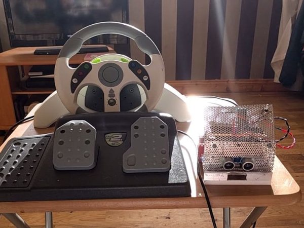
So I’m guessing that I’m like a large amount of people on this site that are low key hoarders, keeping anything they could turn into a project or salvage for parts and this is an example of that. I have this old Mad Catz Steering wheel for the Xbox 360 and now that I have an Xbox one I don’t really have any use for it anymore so decided to use it to control a toy car through Bluetooth. I would’ve liked to connect the USB to a Raspberry Pi but wasn’t sure how to process the information from the USB so I just took it apart, identified the components I could use and designed my own circuit which would be controlled by an Arduino Uno. So in this post, I’ll go through the steps on how I made this project. This is my first project on this site so forgive any mistakes.
Step 1: Components Used
1x Console Steering Wheel
1x Arduino Uno
1x Arduino Nano
1x Toy Car/Build a Robot
2x HM10/CC41-A Bluetooth Modules
1x 2n2551 NPN Transistor
2x 220 Resistors
2x 2.2k Resistors
4x 1K Resistors
1x 220uF Electrolytic Capacitor
1x H-Bridge Chip
1x Switch
2x 9V Battery
Copper Stripboard
Male Headers
Female Headers
Bare Copper Connecting Wire
Assorted Cables
The Steering Wheel doesn’t have to be Mad Catz just any console steering wheel should work. For the toy car I had an old robot I used for a Robosumo competition and I’ll be going through the circuitry and programming for it but not how to build it, in the competition my team mate was in charge of the physical build and details on this can be found at https://davidgreenan.wordpress.com/ I was in charge of circuitry and programming and if you’re interested my OLD blog(current one found here) for the competition can be found here http://www.ronanbyrnesumo.wordpress.com. You could also use one of the many posts on this site to help you build a robot or you could use an old toy car and use that instead of building your own robot, it’s up to you.
Step 2: Open Up the Wheel
Show All Items
Most Likely on the underside of the wheel you’ll find the screws to open the wheel, remove them and make sure to not to lose them because we’ll be closing it up later. When you open it up you’ll see a whole mess of wires connected to a PCB, hopefully you’ll be lucky like me and the board will have all of the wires labelled like in the pictures above. So because there was so many wires going to different parts of the board I grouped each set of wires by putting tape around them and then if I cut the wires from the jumpers so I could match the group of wires to the jumpers. I’d suggest leaving the jumpers in their socket so it’s easy to match the wire to its use.
Once you’ve done that you can trace the wires from the wheel and the pedals, both use potentiometers, these wire just soldered to the board instead of being on a jumper cable but were still labelled for me. The wiper pin of the steering wheel and pedals were marked as follows: Steering Wheel LX, Right Pedal RTR and Left Pedal LTR. The pedals wire can be found on Jumper 6(J6) and the steering wheel isn’t labelled with a jumper but we’ll call it J7. On both jumpers, the positive and negative aren’t labelled but they can be identified by the shape of the solder pad, square for positive and round for negative, for potentiometers the positive and negative don’t really matter. After you identified the wires, make note and unsolder both sets of wires. For this project I only used one button and one LED so that is all I’m going to include in my circuit and code but feel free that add more buttons or LEDs if you want, I used the Xbox Button marked XE on (J4) and the player 2 LED mark LED2 on J5(the player 1 LED was blown). Below I’m going to list the buttons/LEDs going to the steering wheel.
J3:
- Right Bumper = RB
- Left Bumper = LB
- Left Stick Button(LSB) = LT
- Back Button = BA
- Start Button = ST
- D-Pad Right =DR
- Right Stick Button(RSB) = RT
- 3.3V = 3.3V
J4:
- Y Button = Y
- X Button = X
- B button = B
- A Button = A
- Xbox Button = XE
- D-Pad Up = UP
- D-Pad Left = DL
- D-Pad Down = DN for some reason?
- Ground = GND
J5:
- Unknown = MR
- Unknown = ML
- Vcc = Unconnected
- Player 4 LED =LED4
- Player 3 LED = LED3
- Player 2 LED = LED2
- Player 1 LED = LED1
J6:
- Positive = (square pad)
- Left Pedal = LTR
- Right Pedal = RTR
- Ground = (round pad)
J7(This isn’t marked as J7 but anyway):
- Negative = (round pad)
- Steering Wheel = LX
- Positive = (square pad)
Your labels and layout may differ but hopefully there’re some things in common. I couldn’t figure out what MR or ML were so if you know feel free to comment below. The two other jumpers (J1 and J2) on the board are for the USB and mic but I’m not using them in this project.
Step 3: Build Test Circuit and Code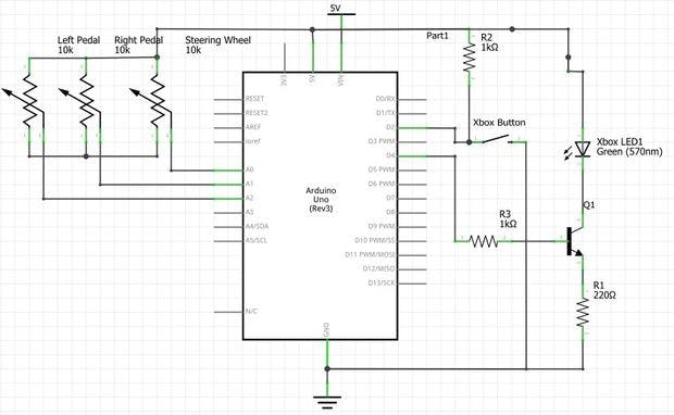
From testing with my multimeter I found that the switches and buttons are connected to ground when pressed and that the LED wires are connected to the negative of the LEDs and the positive is connected to 3.3V on J3. From this I designed this circuit shown above, this is just the test circuit so I didn’t include the Bluetooth module at this stage. The steering wheel ran of 3.3V but to to use the full resolution of the Arduinos ADC I powered the circuit using 5V.
For more detail: Controlling Robot Over Bluetooth Using Xbox Steering Wheel
- Can I use any console steering wheel for this project?
Yes, the article states the steering wheel does not have to be Mad Catz and any console steering wheel should work. - How did the author identify steering and pedal wiring?
They opened the wheel, grouped and taped wires, left jumpers in place to match wires, and traced potentiometer wiper pins labeled LX, RTR, and LTR. - Does the steering wheel run at 3.3V or 5V?
The steering wheel ran at 3.3V, but the author powered the circuit at 5V to use the full resolution of the Arduino ADC. - Which buttons and LEDs were used in the project?
The author used the Xbox Button marked XE on J4 and the player 2 LED marked LED2 on J5; other buttons and LEDs were identified but not all used. - How are switches and buttons wired on the wheel?
Testing with a multimeter showed switches and buttons connect to ground when pressed. - Where are the pedal and steering wiper labels located?
The pedals were on Jumper 6 (J6) labeled LTR and RTR; the steering wiper was labeled LX on an unmarked jumper referred to as J7. - Are the USB and mic jumpers used in this project?
No, the two other jumpers J1 and J2 for USB and mic were not used in this project. - What Bluetooth modules were used to control the robot?
The project used HM10 or CC41-A Bluetooth modules (two of them).