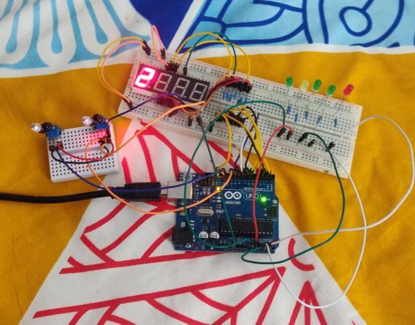
This is a prototype version of the contactless switchboard which helps to control the appliances (AC appliances can be controlled through relays) without touching the actual switches. This can be used in public places like malls, hospitals, etc. In this pandemic time such device can be very useful.
Supplies
- Arduino UNO (Any Arduino Board can be used)
- Cable to connect Arduino to PC
- Breadboard
- Few Male to male Jumper wires
- 7 segment display
- 5 LED s
- 12-15 nos. 220 ohm resistors
- 2 IR Sensors
Step 1: Items Required
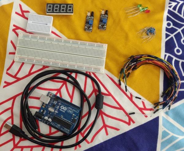
These are the items required for making this project.
Step 2: 7 Segment Connections
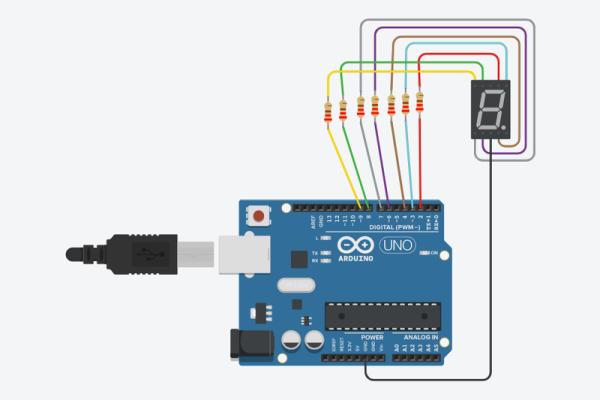
Any 7-segment can be used (common cathode or anode), i have used a common cathode 7-segment display. Single 7-segment can also be used. The pins a,b,c,d,e,f and g of 7-segment are connected to 220-ohm resistors in series and are connected with the 2,3,4,6,7,8 and 9 pins of the Arduino UNO respectively. If you are using single digit, then connect the common pin of the 7-segment with the Arduino GND. In this case i’m using only single digit of the display. The circuit shown in the picture is designed in TinkerCAD.
Step 3: LED Connections
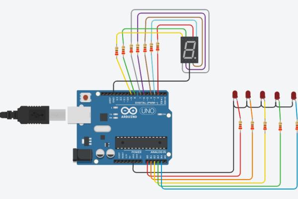
The cathode (shorter leg) of all LEDs is connected to the negative rail of the breadboard which is connected to the Arduino GND. Anode (longer leg) of all LEDs is connected in series with 220-ohm resistor and then is connected to the A0,A1,A2,A3,A4 pins of the Arduino UNO. You can make changes in the code if you want to use other pins or any other Arduino Board. The circuit shown in the picture is designed in TinkerCAD.
Step 4: IR Sensor Connections
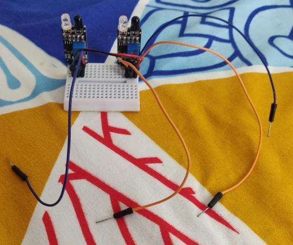
The GND and VCC pins of the IR sensors are connected to the GND and +5V pin of the Arduino UNO. The OUT1 and OUT2 pin is connected to pin 10 and 12 of the Arduino UNO. First IR sensor is used to change the number of appliance to be controlled and the second IR sensor is used to toggle ON and OFF that appliance.
Step 5: Uploading the Code
Upload the following code to your Arduino Board. You can change number of appliances by changing variables in the code. Also, if you want to use third IR sensor to increase and decrease number on 7-segment display uncomment the lines related to ir2 in the code.
Step 6: Have a Try!
See the project in action!
Step 7: What’s Next?
This project can be further reduced in size by designing a PCB and AC appliances can be controlled by using relay modules. Also, it should be noted that this won’t work in outdoor environment where there is direct sunlight but works perfectly fine for indoor environment.
Happy Making!
Source: Contactless Switchboard