Please vote for this Instructable if you think it deserves it! Thanks!
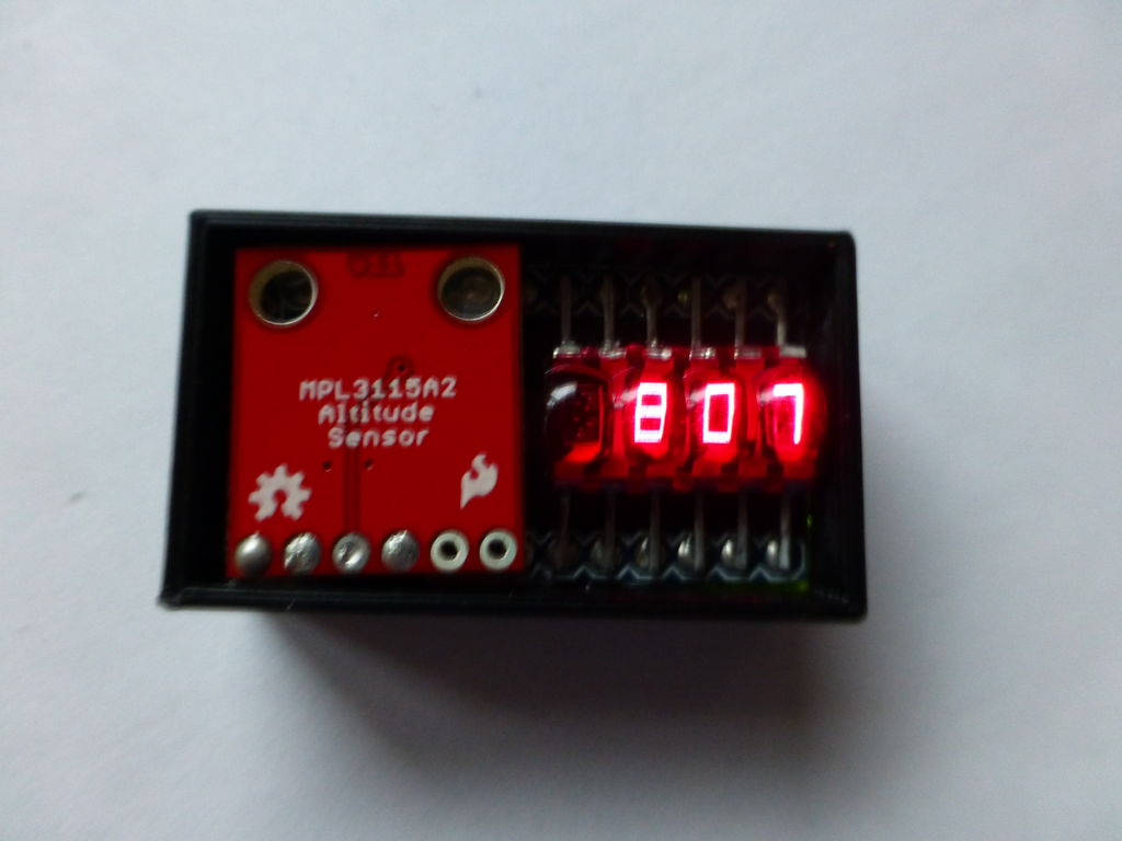
The Ultimate Altimeter is a super-compact, Arduino controlled altimeter capable of measuring the altitude with an accuracy of 0.3 meters, and saving the highest and lowest values it has measured. It is powered by a 40 mAh Lithium Polymer battery, uses a tiny LCD Bubble Display, and measures altitude with a MPL3115A2 Altitude Sensor. It’s very simple and fairly easy to build with just six major components. Additionally, an optional 3D printed case can house the Altimeter.
The Altimeter has a couple of different modes: current altitude, highest altitude, lowest altitude, difference in altitude (highest minus lowest), and standby (turns display off to save power for ~6 hr battery life, not shown in video).
The entire build adds up to around $30, but you may have some or most of the parts lying around already.
You can make this! It is not a very difficult project, and could be good practice for through-hole soldering, and coding (if you want to do modifications). Read on and create!
Step 1: Materials List
Parts:
Tools and other materials:
Soldering iron
Solder
Flush cutters or wire cutters
Wire strippers
Electrical tape
Liquid electrical tape or other insulative paint (you could also use regular electrical tape or heat shrink tubing)
24 guage stranded wire
Hot glue gun
Step 2: Solder the Bubble Display
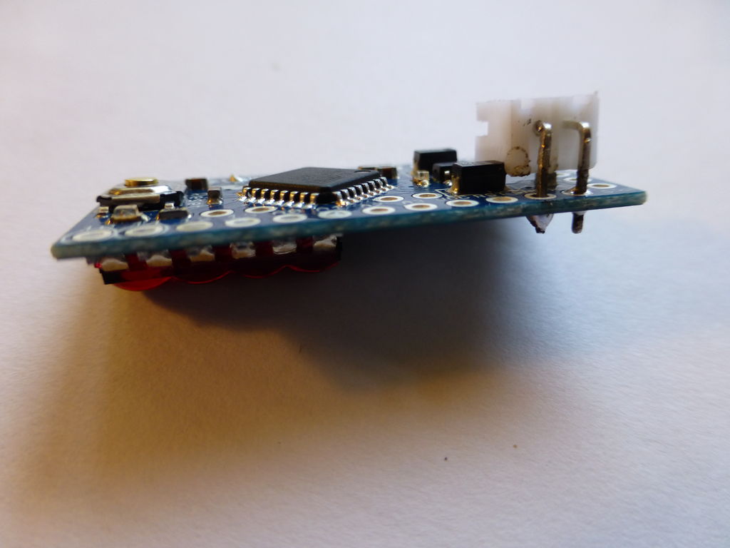
The Bubble Displays are set up to be put into a breadboard, but since we will be soldering it directly onto the pins on the back of our Arduino, the leads need to be bent flat with a pair of pliers. Once bent, rest the display on a flat surface, and make sure it lays flat and all of its leads touch the surface. This will ensure that they will make good contact with the pins on the Arduino.
Next, put down a piece of electrical tape as shown in order to prevent unwanted connections between the board and the display.
Temporarily tape the display down to the Arduino in order to keep it in place while you solder the leads to the corresponding pins on the Arduino. The leads don’t actually go through the holes; they can just rest on top and be connected with solder.
Step 3: Add the Button
Bend out two of the adjacent leads on the button and snip them off. Then solder the remaining leads to GND and PIN 3 on the Arduino.
You can trim the button shaft to the length of your liking. If you a snipping device, the shaft will break uncleanly. I used a thin saw to cut it, and then filed it smooth.
Step 4: Add the JST Connector and Switch
IMPORTANT: Read this whole step before starting it. It is put together strangely because I had to change and fix the project as I built it. Also, there are some things in the photos that haven’t been covered yet because the order in which I built it is different from the order of this Instructable.
Solder the JST connector into the GND and RAW pins on the Arduino. Then, cut the lead that goes to RAW in half. This is where the switch circuit will be added so we can turn the device on and off
Glue the switch into place. Push it right up against the button so there is enough space to program the Arduino with FTDI later. I used superglue to stick it in place. We won’t be using any of the pins that it is covering up so you can glue it right onto the board.
Next, twist the JST connector so it is facing the rest of the board instead of the switch. This will allow the battery to plug in (there wasn’t enough space before). Only one of the leads of the connector is in the Arduino now, so it should be easy to twist. You may need to do some supergluing to get the metal pins that stick into the plastic part of the JST connector to stay in place.
Solder the button into the cut lead of the JST connector as shown in the picture, and you are done with the power circuit!
Step 5: Connect the Altitude Sensor
Connect the Altitude Sensor’s SDA, SCL, VCC, and GND pins to the Arduino’s A4, A5, VCC, and GND pins respectively with stranded wire. This can be tricky. I looped all the wires but the ground wire around underneath the sensor board to make it easier to work with as well as providing extra support to the board to keep it from rocking. I routed the ground wire directly from one GND pin to the other.
Make sure nothing is shorted. If there are any exposed wires that are close to each other, you can slip a piece of electrical tape between them and make sure it sticks.
After testing that your sensor is working and connected properly with some example code, glue it in place with hot glue. The sensor uses air pressure to detect altitude to make sure to leave space for air to reach the sensor. I just glued under each corner.
Step 6: Prepare and Install the Battery
Next, the battery’s wires need to be made much shorter so it will fit in the remaining space we have. Strip, cut and re-solder the wires so that they are very short.
Because of the short length of the wires that you are stripping, the rubber casing of the wire may come off completely. To fix the now-bare wires, I used liquid electrical tape, an insulative paint type material. This will keep the wires from shorting. You could also use heat-shrink tubing or regular electrical tape.
Now, all the electronics are in place. The last thing to do is the code.
For more detail: A compact, Arduino altimeter for RC Planes


