Summary of Cheap Arduino Controled Yogurt Maker
This article describes building an Arduino-controlled yogurt maker to maintain ~43ºC for gallon batches. It covers wiring a 12V 8Ω resistor (18W) as the heater mounted to metal, using a 12V relay module driven by Arduino pin 3, and a DS18B20 temperature sensor on Arduino pin 2 with a 4.7K pull-up. The Arduino runs provided code to read temperature, log to SD, and switch the relay between tempMin (42.5ºC) and tempMax (43.5ºC). The project lists components, costs, and simple assembly tips.
Parts used in the Arduino Yogurt Maker DIY setup:
- Styrofoam box (large enough for yogurt jar)
- 8 Ohm 25W power resistor
- 12V 2A power supply
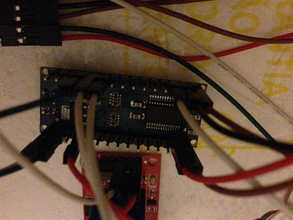
- Arduino Nano board
- 12V relay module for Arduino (with optocoupler)
- DS18B20 temperature sensor
- 4.7K 1/4W pull-up resistor
- Heat sink or scrap metal sheet
- Wiring, solder, and heat-shrink tubing
- SD card module (CS pin to pin 10, MOSI 11, MISO 12, CLK 13)
These days I was reading an interesting post on how to make yogurt “by the gallon,” which explained the need to maintain a constant temperature of about 43ºC (110°F) so the bacteria can grow properly. Commercial yogurt makers are available, but they’re usually too small for producing a full gallon at once. Building your own is not only cheaper but also far more enjoyable. This inspired the idea of creating an Arduino Yogurt Maker DIY setup, allowing precise temperature control and a customized system perfect for large-batch yogurt making.
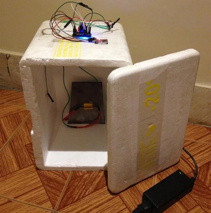
Step 1: Wiring the box
When you apply 12V to the 8 ohm resistor you get a current of 1.5A, wich in turn gives you 18W of heat. This is what’s going to keep our yogurt warm!
In order to better dissipate this heat I screwed the resistor to a piece of scrap metal sheet I had lying around. A better option would be a heat sink+fan from an old computer, but I don’t have one right now…
One wire from the resistor connects to the negative of the power supply, the other one connects to the C (center) connector of the relay. The NO (normally open) connects to the 12V of the power supply.
The 12V relay module has 3 pins: Vin goes to the 12V, GND to the negative and data goes to Arduino pin 3. This module has an optocoupler, which protects the Arduino from any interference from the relay.
In the Arduino Yogurt Maker DIY setup, the Dallas DS18B20 thermometer uses three pins, all of which connect to the Arduino according to its datasheet. One pin goes to GND, the second connects to digital pin 2, and the third goes to the +5V pin. Using thin wire, soldering, and heat-shrink tubing helps create solid, insulated connections. A 4.7K pull-up resistor must be soldered between pin 2 and pin 3 for the sensor to function correctly. Once wired, the thermometer can be positioned inside the box with tape to accurately monitor the system’s temperature.
Step 2: Programing the Arduino
Now it’s time for some programing. Actually you can just copy my code and upload it to the Arduino 😉
/*
Script by Manuel Schutze – May 2013
Connections:
DS18B20 thermometer – pin 2
Relay module – pin 3
SD CS – pin 10
SD MOSI – pin 11
SD MISO – pin 12
SD CLK – pin 13
*/
// Include necessary libraries
#include <OneWire.h>
#include <DallasTemperature.h>
#include <SD.h>
// Setup vars
long intervalTemp = 1000; // interval between temperature measurements
long intervalSD = 5000; // interval between saving data on the SD card
float tempMin = 42.5; // min temp (< truns on heat)
float tempMax = 43.5; // max temp (> truns off heat)
int rele = 3; // pin where the relay is connected
const int chipSelect = 10; // pin CS (SD card)
– Styrofoam box big enough to fit your yogurt jar
– 8 Ohm 25W power resistor (USD 3.80 at aliexpress)
– 12V 2A power supply (got mine from an old laptop)
– Arduino Nano board (USD 11 at dealextreme)
– 12V relay module for Arduino (USD 3.40 at dealextreme)
– DS18B20 thermometer (USD 2.50 at dealextreme)
– 4.7k 1/4W resistor
– Heat sink or piece of scrap metal
– Some wiring
Since I got the Styrofoam box and power supply for free, the total amount I spent on this was less than 21 bucks!
For more detail: Cheap Arduino Controled Yogurt Maker
- How is the heater implemented?
The heater is an 8 ohm resistor supplied with 12V, producing about 18W, mounted to metal for dissipation. - How is the resistor wired into the relay and power supply?
One resistor wire goes to the power supply negative, the other to the relay C (center); the relay NO connects to the 12V supply. - How is the relay module connected to the Arduino?
The relay Vin goes to 12V, GND to negative, and data to Arduino pin 3. - How is the DS18B20 temperature sensor wired?
The DS18B20 pins connect to GND, digital pin 2, and +5V, with a 4.7K pull-up between pin 2 and pin 3 (+5V). - What temperature range does the code maintain?
The code uses tempMin 42.5ºC to turn heat on and tempMax 43.5ºC to turn heat off. - Where does the temperature sensor get placed?
The sensor is taped inside the box to accurately monitor the system temperature. - Does the project log temperature data?
Yes, the provided code includes SD card logging using chip select pin 10 and SPI pins 11, 12, 13. - What protection does the relay module provide for the Arduino?
The 12V relay module includes an optocoupler to protect the Arduino from relay interference.