Summary of Cardboard Spider (DIY Quadruped)
This article details the construction of a simple quadruped robot using accessible materials like corrugated cardboard. The project utilizes an Arduino Nano for the robot body and an Arduino Uno for a remote controller, communicating via NRF24L01 transceivers. Each of the four legs features three joints (coxa, femur, tibia) controlled by micro servos. The builder explains the inverse kinematics used for movement and demonstrates how to stack and glue cardboard layers to create a sturdy frame without 3D printing.
Parts used in the Cardboard Quadruped Robot:
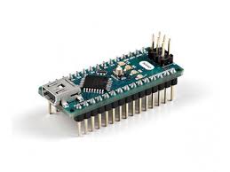
- Arduino Nano Microcontroller
- Deek Robot Nano V03 Shield
- Tower Pro Micro Servo 9g SG90 (12 pcs)
- LED light
- NRF24L01 transceiver (2 units)
- Arduino Uno Microcontroller
- Joystick
- Various resistors
- Push button
- Jumper wires
- Corrugated Carton sheet
- Cutter
- Screw Drivers
- Double tape scotch
- Triangles
- Ruler
- Pencil
Hello again and welcome to my new project.
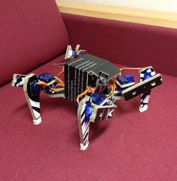
In this instructable I’ve tried to make a simple Quadruped made from materials accessible to everybody. I know to get a good looking final product you need a 3d printer and maybe a CNC, but not everybody has one of this fancy devices, so I tried to demonstrate that with simple material you can still build some nice stuff.
So as mentioned before we will try to build a Quadruped. The frame of the Quadruped will be made simply from corrugated carton this includes the frame, the femur and tibia of each of the four legs.
Step 1: Why Quadruped and How It Works?
I have to say that robots are fun and interesting. I’ve never build a legged robot before so I thought that I should give it a try.
I decided to build a quadruped first off all because I didn’t had enough servos for a hexapod. I’ve imagined if you can build a quadruped then to build a hexapod will be just a step forward. Since this is my first project of this type I didn’t knew exactly what to expect so I thought 4 legs will be easier then 6 but as I found out later this is not always true.
Quadruped having only 4 legs in order to not fell down once one of the legs is lifted the centre of gravity of the robot has to be shifted in the interior of the triangle created between the tips of the other three legs.
A very nice description of all this process you can find here: https://makezine.com/2016/11/22/robot-quadruped-a…
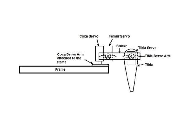
Each leg of the quadruped has 3 joints to control the tip of the leg in space. So the joints will be:
– Coxa servo – between the frame and femur
– Femur servo – controlling the femur of the leg
– Tibia servo – between the femur and tibia controlling the tibia
To know the angle of each servo for the necessary location of the tip of the leg we will use something called inverse kinematics. You can find a lot of documentation on internet about this, and how to calculate the angles of the servos for the different location of the tip of the leg. But in my case I just took the Arduino Code created by RegisHsu (you can find his detailed quadruped instructable if you give it a search) and I’ve changed the dimensions of the robot and the robot legs to fit my robot and also changed the program to use a remote control to control the robot and that’s it.
Step 2: Why Using Corrugated Carton for the Frame and Legs?
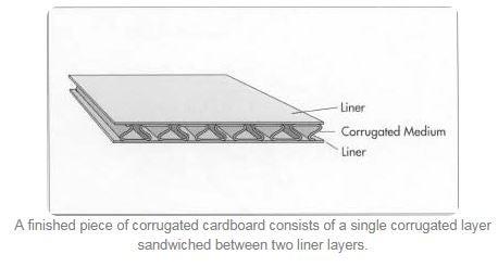
First of all it is widely spread, you can find it anywhere and if you like to buy is very cheap. Corrugated cardboard is a stiff, strong, and light-weight material made up of three layers of brown kraft paper and most of the packing boxes are made from it. So it is very easy to find some.
In my case I used a shoes box which I’ve cut and make the frame out of it. The carton that was provided by my box was a 2 mm thick so it is very thin. So for each part of the frame I’ve had to cut three identical parts and glue them together with double tape scotch. So actually we will have to make 3 frames to have at the end a 6 mm thick carton.
Step 3: Part Required:
Electronical parts required for the Quadruped:
– Arduino Nano Microcontroller;
– Deek Robot Nano V03 Shield – not essential, but it will make the connection of all servos to the Nano Board much easier.
– 12 pcs Tower Pro Micro Servo 9g SG90 – 4 legs with 3 joints each;
– LED – for light ( I used an old burned out colour sensor)
– 1 x NRF24L01 transceiver
Electronical parts required for the remote controller
– Arduino Uno Microcontroller;
– 1 x NRF24L01 transceiver;
– Joystick;
– LED;
– Various resistors;
– Push button;
– Some jumper wires;
For the frame:
– Corrugated Carton sheet
– Cutter
– Screw Drivers
– Double tape scotch
– Triangles
– Ruler
– Pencil
So let’s start building.
Step 4: Setting the Servos on 90 Degrees
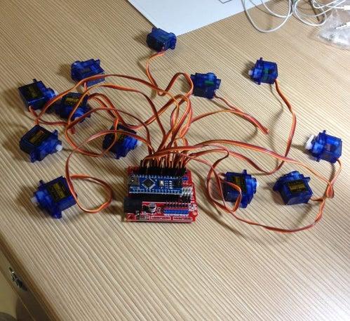
Before starting building the frame I’ve had to center all the servos to 90 degrees so that it will be easier to position them later on when the frame is ready. So I’ve attached first the Arduino Nano intended for the Quadruped to the Nano shield, and after all the servos to the shield. Then all you need to do is upload the code and all the servos will be centered to 90 degrees positions.
The code can be found in the last step of the instructable.
Step 5: Building the Frame
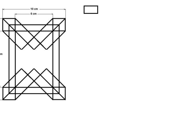
As mentioned before the frame is build out of the corrugated carton provided from a shoes box. The template of the frame you can find in the attached pictures together with dimensions of the frame.
First I cut the sides of carton box to make the frame. I’ve obtained three good pieces for which I took in consideration the orientation of the corrugated layer so that 2 pieces will have vertical cell corrugated layer and one horizontal.
Once the carton was ready, I draw the frame template on the carton sheet which has the vertical corrugated medium. To obtain a stronger more stiff structure I’ve cut three pieces in order to glue them together for extra strength against bending. The upper and lower carton sheets have vertical corrugated layer while the sandwiched carton sheet will be horizontal corrugated layer.
Before I glued the three frame pieces together I prepared the servo motors arm and I draw the position of each coxa servo motor for future correct positioning.
Now that I know where the coxa servos have to be positioned I glued the three pieces together.
Now the frame is done.
Step 6: Attaching the Coxa Servos to the Frame
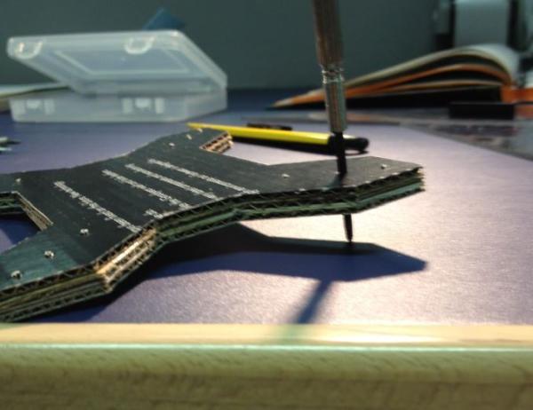
To attach the servos first I pounced a hole in the marked position so that the securing screw for the servo arm will pass, and secure the servo to the frame.
Using the screws provided from the servo motors I’ve attached the coxa servo motors arms to the frame. The coxa is formed from two servos glued together with double tape and reinforced with rubber band just in case. One servo will be orientated downward with the shaft in vertical position and will be attached to the frame, and the other one will be orientated with the shaft in horizontal position and will be attached to the inner side of the femur.
Finally to secure the coxa servo to the frame the securing screw is screwed in.
Source: Cardboard Spider (DIY Quadruped)
- Why was a quadruped chosen over a hexapod?
The author chose a quadruped because they did not have enough servos to build a hexapod. - How many joints does each leg of the quadruped have?
Each leg has three joints: Coxa servo, Femur servo, and Tibia servo. - What material is used to construct the frame and legs?
The frame and legs are made from corrugated carton cut from a shoe box. - How is the strength of the cardboard frame increased?
Three identical pieces of 2 mm thick carton are cut and glued together with double tape to create a 6 mm thick structure. - What method is used to calculate servo angles for leg movement?
The project uses inverse kinematics to determine the angle of each servo for the necessary location of the leg tip. - Which code source was adapted for this project?
The author used Arduino Code created by RegisHsu, modifying dimensions and adding remote control functionality. - How are the servos prepared before building the frame?
All servos are centered to 90 degrees using an uploaded code before attaching them to the shield. - How is the coxa servo assembly constructed?
The coxa is formed from two servos glued together with double tape and reinforced with a rubber band.