Summary of Blink an LED With Arduino in Tinkercad
This article guides beginners on blinking an LED using an Arduino Uno, either via the Tinkercad Circuits simulator or with physical hardware. It details connecting an LED and resistor to digital pin 13 and ground, explains the necessary code structure using both block-based and text-based syntax, and provides steps for uploading the sketch to a real board.
Parts used in the Blink an LED Project:
- Arduino Uno board
- LED (Light Emitting Diode)
- Resistor (100 to 1000 ohms, recommended 220 ohms)
- USB cable
- Computer with Arduino software
- Tinkercad Circuits (browser-based simulator)
Let’s learn how to blink an LED (light emitting diode) using Arduino’s digital output. If you’re new to Arduino, this is a great place to start. We’ll connect an LED to the Arduino Uno and compose a simple program to turn the LED on and off.
You can follow along virtually using Tinkercad Circuits. You can even view this lesson from within Tinkercad if you like! Explore the sample circuit and build your own right next to it! Click “Start Simulation” to watch the LED blink. You can use the simulator any time to test your circuits. Tinkercad Circuits is a free browser-based program that lets you build and simulate circuits. It’s perfect for learning, teaching, and prototyping.
Find this circuit on Tinkercad
If you want to follow along with your physical Arduino Uno (or compatible) board, you’ll also need a USB cable and a computer with the free Arduino software (or plugin for the web editor) installed, and optionally a single LED.
Step 1: LED Resistor Circuit
The LED’s legs are connected to two pins on the Arduino: ground and pin 13. The component between the LED and pin 13 is a resistor, which helps limit the current to prevent the LED from burning itself out. Without it, you’ll get a warning that the LED might burn out soon. It doesn’t matter whether the resistor comes before or after the LED in the circuit, or which way around it goes. The colored stripes identify the resistor’s value, and for this circuit, anywhere from 100 ohms to 1000 ohms will work great.
The LED, on the other hand, is polarized, which means it only works when the legs are connected a certain way. The positive leg, called the anode, usually has a longer leg, and gets wired to power, in this case coming from your Arduino’s output pin. The negative leg, called the cathode, with its shorter leg, connects to ground.
In the Tinkercad Circuits components panel, drag a resistor and LED onto the workplane. Edit the resistor’s value by adjusting it to 220 ohms in the component inspector which appears when the resistor is selected. Back in the components panel, find and bring over an Arduino Uno board. Click once to connect a wire to a component or pin, and click again to connect the other end. Connect your resistor to either side of the LED. If you connected your resistor to the LED’s anode (positive, longer), connect the resistor’s other leg to Arduino’s digital pin 13. If you connected your resistor to the LED’s cathode (negative, shorter leg), connect the resistor’s other leg to Arduino’s ground pin (GND). Create another wire between the unconnected LED leg and pin 13 or ground, whichever is still not connected.
Extra credit: you can learn more about LEDs in the free Instructables LEDs and Lighting class.
If you have a physical Arduino Uno (or compatible) board, you may plug an LED directly into pin 13 (positive, longer leg anode) and ground (negative, shorter cathode), because pin 13 actually has a built-in resistor for exactly this testing purpose.
Step 2: Simple Code With Blocks
In Tinkercad Circuits, you can easily code up your projects using blocks. Let’s go through the simple code controlling the blink by opening the code editor (button labeled “Code”). You can resize the code editor by clicking and dragging the left edge.
The code starts out with two gray comment blocks, which are just notes for us humans to read. The first blue output block sets the built-in LED HIGH, which is Arduino’s way of describing “on.” This output command will activate a 5V signal to anything connected to the specified pin. Next up is a a yellow command block that waits for one second, simple enough. So the program will pause while the LED is on for one second. Next after another comment is a blue output block to set the LED back to LOW, or “off,” followed by another second-long pause.
Try customizing this code by changing the wait times, and clicking “Start Simulation”. You can even add more output and wait blocks to create longer flashing patterns.
Did you notice the small LED flashing on the board itself? This built in LED is also connected to pin 13, and is meant to be used for testing purposes without the need to connect any external components. It even has its own tiny resistor, soldered directly to the surface of the board.
Ready to create your own? Click to select the Arduino you added to the workplane (or select it from the dropdown menu in the code editor) and start dragging code blocks to create your own blinking program.
Step 3: Blink Arduino Code Explained
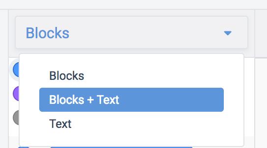
When the code editor is open, you can click the dropdown menu on the left and select “Blocks + Text” to reveal the Arduino code generated by the code blocks. All the extra symbols are part of Arduino’s syntax, but don’t be intimidated! It takes time to learn to write proper code from scratch. We’ll go through each piece here, and you can always use the blocks for comparison as you level up.
/*
  This program blinks pin 13 of the Arduino (the
  built-in LED)
*/
This first section is title block comment, describing what the program does. Block comments are bookended by an opening /* and closing */.
void setup()
{
  pinMode(13, OUTPUT);
}
Next is the code’s setup, which helps set up things your program will need later. It runs once when the program starts up, and contains everything within its curly braces { }. Our blink sketch’s setup configures pin 13 as an output, which prepares the board to send signals to it, rather than listen.
void loop()
{
  // turn the LED on (HIGH is the voltage level)
  digitalWrite(13, HIGH);
  delay(1000); // Wait for 1000 millisecond(s)
  // turn the LED off by making the voltage LOW
  digitalWrite(13, LOW);
  delay(1000); // Wait for 1000 millisecond(s)
}
The main body of the program is inside the loop, indicated by another set of curly braces { }. This part of the code will execute on repeat, so long as the board has power. The colored text following double slashes are also comments to help make the program easier to understand. The output command we’re using is called digitalWrite(), which is a function that sets a pin HIGH or LOW, on or off. To pause the program we’ll use delay(), which takes a number of milliseconds (1000ms = 1s).
Step 4: Use the Blink Circuit Starter
This is a circuit we think you’ll want to make frequently, so it’s saved as a circuit starter!
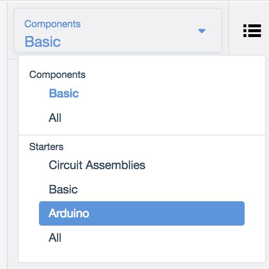
Grab this circuit and code combo any time using the starter available in the components panel (dropdown menu -> Starters -> Arduino).
For a more advanced version of this Arduino code, also check out the Blink Without Delay starter, which uses the current time to keep track of blink intervals instead of delay();
Step 5: Programming a Physical Arduino
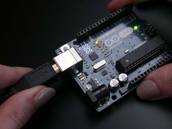
To program your physical Arduino Uno, copy the code from the window and paste it into an empty Arduino sketch, or click the download button and open the resulting file using your Arduino software.
This beginner example is also available directly within the Arduino software under File-> Examples-> 01.Basics-> Blink.
Plug in your USB cable and select your board and port in the software’s Tools menu.
Upload the code and watch your onboard LED flash with the custom blink you created earlier! For a more in-depth walk-through on setting up and programming your physical Arduino Uno board, check out the free Instructables Arduino class (first lesson).
Source: Blink an LED With Arduino in Tinkercad
- How do I connect the LED to the Arduino?
Connect the longer positive leg (anode) through a resistor to digital pin 13, and the shorter negative leg (cathode) to the ground pin. - Can I use a resistor value other than 220 ohms?
Yes, any resistor value between 100 ohms and 1000 ohms will work great for this circuit. - Does it matter which side of the LED the resistor is placed on?
No, it does not matter whether the resistor comes before or after the LED in the circuit. - What function turns the LED on in the code?
The digitalWrite(13, HIGH) command sets the pin to a 5V signal to turn the LED on. - How long does the LED stay on by default?
The LED stays on for one second because the delay function is set to 1000 milliseconds. - Is there a built-in LED on the Arduino board?
Yes, there is a built-in LED connected to pin 13 that has its own tiny resistor soldered directly to the board. - Where can I find the Blink example in the Arduino software?
You can find it under File-> Examples-> 01.Basics-> Blink. - How do I change the blink speed in the simulation?
You can customize the code by changing the wait times in the yellow command blocks.