Using the magic of Arduino, I revived an antique Bell model 202 telephone and added Bluetooth capability to it.
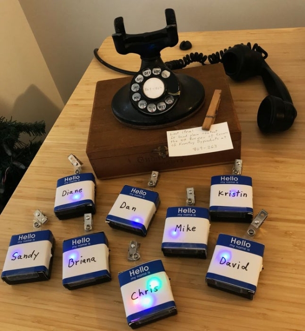
There are two parts to this. On one end I have an ancient phone from the 1930’s. On the other end, I have one of a dozen “name tags” with hidden LEDs. When a person dials the correct number on the phone, a bluetooth connection is made to a name tag pinned to a person’s lapel. When the connection is made, the phone plays a funny message and the name tag flashes in all sorts of crazy colors.
As Arduino projects go, this one is quite complicated but full of gems. This Instructable will show you how to do all of the following:
- Capture numbers dialed on a rotary telephone.
- Debounce noisy switches.
- Play sounds found on an SD Card wired to an Arduino.
- Arduino bluetooth with a Bluno Nano and Buno Beetle.
- Serial connection between two Arduinos using only two digital pins.
- Gently glow an LED so it feels relaxing and “natural”. (An extremely nice feature often overlooked in designs.)
- Wildly blink an orchestra of colors in an interesting attention-grabbing pattern.
I created this as a Christmas game. The game is all about matching a present to a person. Gifts under the Christmas tree are labeled with a 6-digit “phone number”. Someone dials the phone. Magic bluetooth signals talk to a name tag hanging from a person’s shirt. If your name tag lights up like crazy, the gift is for you — go ahead and open it!
If you enjoy “escape room” experiences you will enjoy this. If you’ve never heard of “escape room” I’m sure you will like it too!
You can find all 30+ years of these kinds of gadgets from Christmases past at madwrapper.com .
Step 1: Phone Parts
Phone Parts
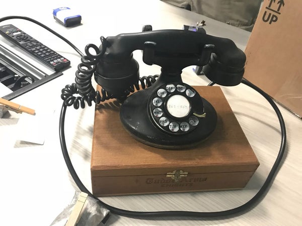
- Bell model 202 telephone (or any dial telephone from 1930 to 1970)
- Antique wooden Cigar box
- DF Robot Bluno Nano (DF Robot)
- Deek-Robot Nano Terminal adapter (Amazon)
- SPI Micro SD Card Reader (Amazon)
- Micro SD Card (Amazon)
- 220 Ohm resistor (connected to the headset speaker)
- 2x 10K Ohm resistors (connected to phone dial)
- Female power jack (Amazon)
- 5V (or up to 12V) power supply (Amazon)
Step 2: Name Tag Parts
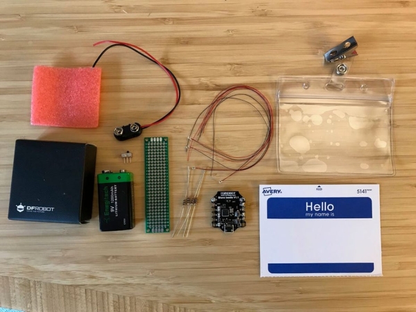
This is the list of items to make one name tag. I made 10 of them.
(Note: I short-circuited one of mine rendering it partially dysfunctional. Plan ahead: maybe order an extra one or two blunos or come up with a plan “B” in case you break one too!)
- DF Robot Bluno Beetle (DF Robot)
- 4x 100 Ohm Resistors (Amazon)
- Blue wearable LED (Amazon)
- Red wearable LED (Amazon)
- Yellow wearable LED (Amazon)
- Green wearable LED (Amazon)
- 9V Double capacity (1200mAh) Lithium Battery (Amazon)
- 9V Battery connector (Amazon)
- Miniature switch (Amazon)
- A 2cmx8cm proto board (cut in half) (Amazon)
- Name tag holder with clip (Amazon)
- Avery 5141 “Hello my name is” Name Tag (Amazon)
Step 3: Wiring the Phone
The arduino inside the phone needs to perform all of the following tasks. This section describes how to wire everything together.
- Turn on the Arduino when someone picks up the headset
- dial the phone
- grab sounds from an SD Card
- play sounds on the headset speaker
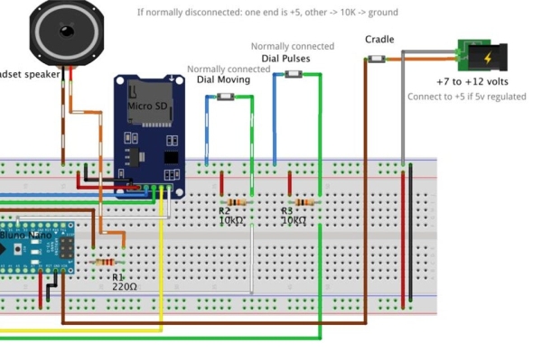
Schematics
Attached are schematics both as raw images and in Fritzing format. You can download the Fritzing app here: fritzing.org
Dialing and Power Switches
There are three switches inside the phone that need to be connected.
- “On-hook” switch that applies power to Vin on the Bluno Nano.
- When the receiver is placed on the hook, this switch is disconnected.
- “Actively Dialing” switch that indicates that the wheel is not in its home position. This is wired to cause pin D8 to be +5v when active and 0v when not.
- On my phone this switch is normally connected when the phone is in its resting position. As soon as the user starts moving the dial, the switch disconnects. I attached one end to ground on the Arduino. I connected the other end to D8 on the arduino. D8 is also connected to a 10K Ohm resistor to +5. This configuration generates a “high” enable signal to tell the Sketch program it is time to start counting pulses.
- (On some other phones this switch is normally disconnected when the dial is “resting”. If you have that type of phone you will need to wire it opposite from mine: one end to +5, other end to D8 and a 10K resistor that goes to ground.)
- “Pulse” switch that generates a pulse every time the dial passes a number as it travels from release back to the home position. This is wired to generate +5V pulses on pin D7.
- On my phone this switch is normally connected when the dial is “resting”. After the user releases the wheel this switch disconnects each time it passes a number. I attached one end to ground on the Arduino. I connected the other end to D7 on the arduino. D7 is also connected to a 10K Ohm resistor that leads to +5 causing the pin to be pulled high when the switch disconnects. This configuration generates “high” pulses for the Sketch program to count.
- (On some other phones, this switch is normally disconnected when the dial is “resting”. If you have that type of phone you will need to wire it opposite from mine: one end to +5, other end to D7 and a 10K resistor to ground.)
I did not add any special circuitry such as a capacitor for debouncing. I handled this with software. Every time the switch opens or closes, you will get a bunch of spikes of electricity (++++-+-+-+-+-+——-) until it settles. The software just waits until the value on the input pin settles to one voltage or another for a long enough period of time before deciding that the state has actually changed.
The Earpiece Speaker
The output pin for generating sound needs to be a pin with PWM capability. Additionally, depending on which Arduino you are using, you may need to pay attention to the timer needed for running the PWM and possibly enable it. Pin D9 on the Arduino Nano (Bluno Nano in my case) is a good default choice since this is configured correctly by default.
There are three wires that go into the headset. Simplifying, these are: ground, earpiece, and mouthpiece. It’s not quite that simple since the earpiece and mouthpiece are loosely connected. I put my voltmeter to “on” position for measuring resistance. In this mode the voltmeter generates a small amount of electricity that produces a “static” scratchy sound in the earpiece when you probe the correct two terminals.
Connect one terminal to ground. Connect the other terminal to a 220 Ohm resistor that leads to D9 PWM pin. This was perfect for the sound level I wanted in the standard telephone earpiece speaker.
(If you want to create a “speaker phone”, you will need to add some extra circuitry to amplify the sound into an external speaker for all to hear. I did not do this in my implementation but would have been a nice enhancement.)
(If you want to add volume control, you can connect a potentiometer to one of the analog input pins and adjust sound level based on input voltage reading.)
Micro SD Card SPI
SPI is straightforward to wire into the Arduino Nano. GND to GND, +5 to +5, MISO to MISO, MOSI to MOSI, and SCK to SCK. I used pin D4 as my select pin so: D4 to CS. (If you are using a 5v Arduino such as a Nano, make sure you use a 5v SD Card controller.)
Wires
I cut a section of cat-5 Ethernet cable and ran it from the connectors on the phone through a hole drilled into the base down to the Arduino housed underneath in a cigar box. The 8 wires in the Ethernet cable were more than enough for my connections and should be enough for any standard dial phone. 8 wires were over-kill for me since I connected all grounds together inside the phone and only ran one ground down to the Arduino. I did not need to run a +5 wire up to the phone, but you may find it necessary to do that if you use a different type of phone. Either way, 8 wires should be more than enough for almost any project.
I also drilled a small hole in the back of the cigar box which allowed me to pass a power cable in after I cut the end off it. The end is spliced back together inside the box then connected to the power supply.
Expose the USB Connector for Programming
I completely wrapped the Nano with electrical tape, leaving only the USB connector exposed and accessible for programming. If you decide to leave the USB cable inside the box even when you are not programming, you must ensure that the end of the cable is isolated from all electrical parts. Static electricity will mess up the electronics causing strange things to happen such an unexpected resets or worse.
Analog pin A0
Note: do not connect anything to pin A0. This pin is used to seed the random number generator so it needs to float unconnected.
Optional: two Arduinos to offload sounds
I’ve provided a schematic if you need to offload sounds to a second Arduino. Do this if you run out of RAM or need to boot faster. A standard Arduino Nano handles the sound. A Bluno Beetle handles dialing and Bluetooth connection.
Wire the two Arduinos together: D2 to D2, and D3 to D3.
Source: Bell Model 202 Bluetooth Telephone (1930-2018)