Summary of Arduino Star-Finder for Telescopes
This project builds an Arduino-powered star-finder handset for a small Dobsonian reflecting telescope. Using a GPS module for time and location, stored Ra/Dec coordinates, and sidereal-time calculations, the system computes target altitude and azimuth. Potentiometers on the telescope measure heading and elevation; LEDs on the handset guide the user to move the telescope until the object is within the eyepiece field of view. Components are housed in 3D-printed fittings and a handheld control box. The design balances cost and usability versus motorised Go-To systems.
Parts used in the Arduino Star-Finder:
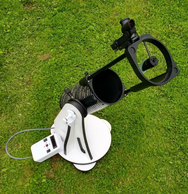
- Skywatcher Heritage 130p Flextube Dobsonian Telescope
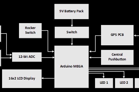
- Arduino Mega 2560 Microcontroller Board
- Adafruit ADS1015 12-bit ADC (analogue to digital converter)
- 16x2 LCD Display (Winstar WH1602B-RTI-JT Red Characters used)
- GPS Module (GY-GPS6MV2 used)
- Battery holder for 6 AA cells (9V total)
- Small breadboard sized to fit inside control box
- SPST Rocker Switch with red LED
- SPST Momentary Pushbutton Switch with red LED
- Four red LEDs
- SPDT Rocker Switch, Centre Off
- One continuous rotation potentiometer for Azimuth (heading)
- One potentiometer for Altitude (inclination)
- Rubber tube to tether handset to telescope mount
- Jumper leads, multicore wire, solder, and resistors for LEDs
- 3D printer filament and 3D-printed fittings (control box, potentiometer holders, battery box holder)
- Arduino Uno (for testing, optional)
Space is big. Really big. Owning a small telescope can give a lot of pleasure, but it’s often a struggle trying to locate specific objects in the night sky. In this project I made and integrated an Arduino-powered star-finder with a small reflecting telescope, to allow me to easily find the galaxies, nebulae and clusters that I wanted to observe.
What: This device calculates the current position in the night sky of a list of galaxies, nebulae and star clusters. It then measures the current heading and elevation of the telescope, and displays to the user how to orientate their telescope so that the chosen target object will be visible. The electronics are all contained within a convenient handset, attached to the telescope mount on a 0.5m cable.
Why: Traditional methods of finding objects in the night sky (using charts, maps, following constellations) are slow and require experience, and motorised ‘Go-To’ telescopes are very expensive. This project finds a happy medium between the two. Clear night skies are not common, so using this Arduino star-finder allows you to make the most of your precious viewing time.
How: The Arduino receives position and time data from a small GPS module. Using this, and known coordinates for a list of objects (my initial code includes 45 astronomical objects, and it’s easy to expand this list if you choose), their current position in the night sky (relative to the observer) is calculated. The name, position and type of the current chosen object are displayed on a small LCD screen on the handset. By using a rocker switch, the observer can choose which of the database’s objects to observe. The heading and elevation of the telescope are measured using potentiometers. The Arduino then compares the position of the target object to the orientation of the telescope, and using LEDs on the handset indicates to the user whether the telescope must be moved up, down, left or right. When the target object is within the field of view, all four LEDs will illuminate. At this point the observer may view the target object through the telescope. The program constantly updates the position information, to assist the observer in tracking the target object as it moves across the night sky. I used a 3D printer to create fittings to house the potentiometers, and to make the handset and battery box holder.
Edit 2020 – new project video!
Please note: this project assumes some prior experience with Arduino, basic amateur electronics, 3D printing and CAD (possibly). I’ve tried to cover all of the background information relating to the astronomy, and justifications about why I designed it how I did. To avoid creating an overly wordy Instructable I’ve therefore left out some minutiae of the project that would be tedious, for instance wiring of LEDs and switches etc. If there’s anything that confuses you, please ask a question and I’ll try and answer. Also don’t forget that the wonderful thing about Arduino is the huge level of online support, so if you’ve got a question, however basic, hopefully you’ll quickly find an answer online too. This is also my first Instructable, so please go easy on me!
**Caution**: when building and testing your telescope star-finder, please take immense care to not view the Sun through the telescope at any time. Doing so will cause permanent eye damage.
Step 1: The Theory
(I’m sure you’re interested about the astronomy principles which this Instructables project uses, but if you’re not, then please skip ahead a step or two).
The methodology for calculating the azimuth and altitude values for the desired object is well detailed in a book called ‘Practical Astronomy with your Calculator or Spreadsheet’ by Peter Duffett-Smith. I’d thoroughly recommend this book for any amateur astronomer, as it shows you how to calculate many different things. Recent editions even show you how to implement the calculations in spreadsheets.
Input Data:
The inputs to the calculation are as follows: the ‘right ascension and declination’ coordinates for the target object, geographical latitude and longitude of the observer, and the current time and date.
Date and time are received by the GPS module, and time is given as Universal Time (UT). Significantly, Universal Time as measured by a GPS system has never been adjusted for leap seconds since the system was initialised in 1980, hence GPS time is currently 18 seconds ahead of true Universal Time. The Arduino GPS library program compensates for this by automatically subtracting 18 seconds from the recorded time to find Universal Time as necessary for the calculations.
Time Systems:
The initial part of the mathematics is concerned with converting UTC to Local Sidereal Time (LST), which is done via Greenwich Sidereal Time (GST). Sidereal Time is defined as the hour-angle of vernal equinox. GST is the Sidereal Time as observed on the Greenwich meridian (0° longitude). The conversion to LST takes into account the longitude of the observer, as the sidereal time gets earlier or later depending on position relative to the Greenwich meridian.
All relative positions of all astronomical objects are located according to the angles of right ascension and declination (Ra/Dec). These two angles locate the object on the celestial sphere, according to the equatorial coordinate system. As the coordinate system gradually moves (as the shape and orientation of the Earth’s orbit changes gradually), the Ra/Dec coordinates are adjusted. This adjustment is performed in relation to the current astronomical epoch. Presently, the J2000 epoch is current, and the Ra/Dec figures for all astronomical items will be quoted for the J2000 period. The Ra/Dec data is combined with the LST figure to calculate hour-angle (Equation 1). Equations 2 and 3 are then used to determine the current altitude and azimuth of the target object. Azimuth and Altitude are the coordinates of the horizon coordinate system. This is a coordinate system unique to that position on the Earth’s surface, where 0° of altitude is the observer’s horizon. When considering the alignment of a telescope to these coordinates, altitude is analogous to the inclination of the telescope, and azimuth is analogous to the heading.
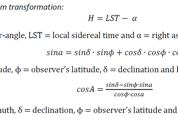
Coordinate system transformation:
(1) H=LST- α
Where H = hour-angle, LST = local sidereal time and α = right ascension.
(2) sina=sinδ∙sinϕ+cosδ∙cosϕ∙cosH
Where a = altitude, ϕ = observer’s latitude, δ = declination and H = hour-angle.
(3) cosA= (sinδ-sinϕ∙sina)/(cosϕ∙cosa)
Where A = azimuth, δ = declination, ϕ = observer’s latitude and a = altitude.
You will see these formulae being used in the Arduino program shown in a later step.
Step 2: The Implementation
How to do this with affordable amateur equipment?
Small GPS modules are easy to use with Arduino, and provide time and location data. Using this, the Arduino can calculate the position of a given galaxy/nebula/cluster at any time. To provide feedback to the user about where to point the telescope, the system will need to measure the current position of the telescope, compare this to the correct positioning, and then tell the user how to adjust the telescope so that it will be pointing at the astronomical object. To measure the position of the telescope, we will use potentiometers. Potentiometers are rotary devices whose electrical resistance changes over their range of rotation. By calibration, these can be used to determine where a telescope is currently pointing, using one potentiometer to measure the telescope’s rotation, and one to measure the elevation. The telescope purchased for this project has a Dobsonian mount, and this is vital! A Dobsonian mount (developed by the legendary amateur astronomer John Dobson – have a look for his videos on YouTube, you will want to try grinding your own mirrors and other amazing things) allows the telescope tube to rotate horizontally and tilt vertically, compared to the complex movements of other telescope mounts. This will make it very straightforward for us to program and measure.
Achieving AccuracyThis was the challenging bit, and required weeks of experimentation. Luckily I’ve done this so that you don’t have to! There are four main quanitifiable sources of error in this system, and they must be managed to ensure that the telescope will manage to find what we want. Firstly, let’s calculate the Field of View (FOV) of our telescope.
Key specifications:
- Focal length of telescope: 650mm
- Focal length of eyepiece lens: 25mm
- Apparent Field of View: 50 degrees
Magnification = (Focal length of telescope)/(Focal length of eyepiece) = 26x
True FOV = (Apparent Field of View)/(Magnification) = 1.923 degrees
So what this means is that when using the ‘Super 25’ eyepiece lens, you will see an area of the sky 1.923 degrees across. Therefore we need to make sure that the device is accurate enough to always locate an object within this angle. So to make sure that the device would work, I tried to quantify each source of error, and do some statistics to predict the performance of the system. You don’t need to do this step unless you’re also interested.
1. GPS Accuracy
This was my first time working with GPS and Arduino together. To assess the accuracy of the unit, it was necessary to compare the GPS module’s output latitude and longitude figures to the latitude and longitude of a known location.
The location of trig points, or triangulation stations, are precisely listed by the Ordnance Survey, the UK’s mapping agency. I took the GPS unit to six of these locations, and test results were taken, so that the device’s figures could be compared to the known OS coordinates. Repeating this test a few times gave me enough results to provide a mean figure of GPS accuracy, which was 11.6m. Using a formula called the Haversine Formula, again from Practical Astronomy with your Calculator, I could find that this should affect the overall telescope alignment by an almost non-existent 0.000581 degrees. Clearly this was not going to be the issue!
2. Potentiometers
In this project, we’re using potentiometers to measure the angle and heading of the telescope. This is potentially a large source of error, firstly from the potentiometers themselves (including quality of the pots, plus the quality of their installation into the telescope mount), plus how we read this data with the Arduino. An affordable magnetometer and gyroscope unit (the 1120 3-Axis Accelerometer and Magnetometer from Adafruit) was tested, but was found to have an accuracy of greater than 1°, insufficient for this purpose. Optical encoders do not have a sufficiently high resolution if used in a 1:1 ratio with the movement of the telescope, and would therefore require a gear system to raise the number of counts per degree of movement, hence why potentiometers with a linear resistance output were chosen.
So what will be their resolution? To work this out we need to look at how the Arduino measures the analogue signal from the potentiometers. The ATmega2560chip of the Arduino has a 10-bit analogue to digital converter (ADC), which means that the voltage reading from the potentiometer is mapped onto a set of discrete values from 0 to 1023. The number of integer values within this range is what determines the maximum resolution of the potentiometer reading.
The potentiometer selected for measuring the rotation of the telescope, a 6187R 1 KΩ Single Turn Precision Potentiometer from TT Electronics has an electrical travel over 340°. To find the angular resolution we divide 340° by the 1024 intervals, using equation 6, and see that the angular resolution is 0.332°. This is equivalent to 17.2% of the width of the field of view using the 25 mm eyepiece lens. To improve the resolution of the potentiometer readings, an external 12-bit ADC, the ADS1015 4-channel ADC from Adafruit was selected. This small module performs the analogue to digital conversion, and supplies the Arduino with the digital readout. The new range of output discrete values is between 0 and 1660. This seemed to be the best compromise between the Arduino’s 10-bit ADC and the Adafruit 14-bit ADC that is also available. The elevation of the telescope will have a greater resolution, as the telescope is being rotated over a smaller arc than it is in being rotated in heading. This results in an error of 0.10 degrees in heading, and 0.077 degrees in pitch, so not a big deal either.
3. Accuracy of Ra/Dec Data
For each of the 45 objects in the database (16 clusters, 20 nebulae and 9 galaxies), the figures for the J2000 right ascension and declination coordinates were taken from the HyperLeda database. This source quotes the accuracy of the coordinates is 10 arcseconds (0.00277°). The reason for this inaccuracy is likely because of the difficulty of determining the centre of these astronomical objects in order to define their position, as many of them are rather amorphous in shape. Object 19 in the database for instance, the Crescent Nebula, has an apparent width of 0.33° and an apparent height of 0.17°. As it has an irregular shape, it is not possible to accurately determine the true centre of the object, hence a partial explanation for the inaccuracy in the Ra/Dec data.
4. Program Error
By far the greatest source of error was generated by the Arduino and its program. I’m sure a better programmer could reduce this significantly, but I’m a relative amateur, and found managing the large numbers, decimals and all the associated arithmetic quite challenging. To assess the magnitude of this, the Arduino results were compared to position results calculated in Microsoft Excel, and it was found that the mean error was 0.72 degrees.
SUMMARY: Overall Error
In Excel, each of the four identified sources of error was independently randomised, then combined to produce this graph (heading image of this step). That image shows 5000 randomised results and their distribution within the FOV of the telescope. Results within that black circle would be visible to the observer. The analysis was performed so that the errors may partially cancel each other out, as would be the case in reality. 81.94% of these theoretical points fall within the field of view. Whilst not perfect, this seemed good enough in my mind to continue with the practical details of the project.
Step 3: Ingredients
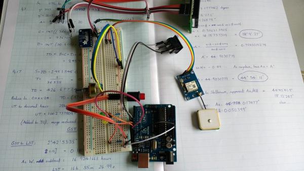
Here’s the list of components I used for this project (note that the above image only pictures a few of them, that’s just a shot of my GPS test setup). With the exception of the major components, I haven’t specified a particular product or supplier. This is because that might not be helpful to people who like in a different country to me, and also because for many of these components (switches etc.) it doesn’t hugely matter what you use.
- Skywatcher Heritage 130p Flextube Dobsonian Telescope
- Adafruit ADS1015 12-bit ADC (analogue to digital converter)
- 16×2 LCD Display (I used Winstar WH1602B-RTI-JT Red Characters)
- Arduino Mega 2560 Microcontroller Board
- GPS Module (I used GY-GPS6MV2)
- Battery holder for AA batteries (6 cells in series to produce 9V)
- Small breadboard to fit inside the control box
- SPST Rocker Switch with red LED
- SPST Momentary Pushbutton Switch with red LED
- Four red LEDs
- SPDT Rocker Switch, Centre Off
- Rubber tube to use as hose to connect the handset to the telescope mount.
- Arduino Uno (not part of the finished device, but useful to have a second Arduino for testing purposes)
- Suitable resistors to use with each of the LEDs.
- One continuous rotation potentiometer for measuring the Azimuth (Heading) of the telescope.
- One potentiometer for measuring the Altitude (Inclination) of the telescope.
You’ll also need jumper leads of different lengths and types, multicore wire, solder, insulation tape, filament for your 3D printer, and a computer with the Arduino IDE software installed to allow you to program the Arduino.
Step 4: Additions to the Telescope Mount
For this project, we need to add a variety of pieces to the telescope mount. I’ve included .step files of these parts in the next step of this Instructable. I’ve added them as .step rather than .stl as .step files are more easily modifiable if you want to import them into your own CAD software, and if you want to convert to .stl files for 3D printing, then there are several free online converters that allow you to do this easily. Note that these files are designed to fit the Dobsonian telescope that I owned, but if you would like to implement this system for a different Dobsonian telescope you will need to adapt at least the potentiometer holders, although the design principle will be the same.
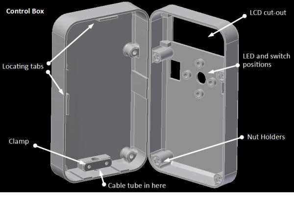
Control Box (1st Image, consists of 3 pieces)
This consists of two shell halves, plus a small piece which is used inside to clamp the tube that tethers the control box to the telescope mount. That clamp piece is bolted across the tube, compressing it and holding it in place.
Telescope Altitude Axis Potentiometer Holder (2nd Image, consists of 3 pieces)
The Skywatcher telescope I bought came with a tensioning knob. You loosen this to adjust the inclination of the telescope tube, then tighten it off to stop it sagging freely. I replaced this with a 3D printed one, which accepts the shaft of a potentiometer on the other end. The body of the potentiometer is then held by a cup shape attached to a stem which sits on the shoulder of the telescope mount. The purpose of this is to rotate the shaft of the potentiometer relative to the body of the potentiometer as the telescope tilts (allowing us to measure its angle).
Telescope Azimuth Axis Potentiometer Holder (3rd Image, consists of 4 pieces)
Similarly, this assembly is used to mate a potentiometer to the rotation of the telescope, relative to the telescope mount’s base. The Skywatcher telescope I modified has a central bolt. I added the small printed part underneath to stop it rotating relative to the telescope baseplate. The pieces above mate the shaft of the potentiometer to that bolt, and the body of the potentiometer to the upper surface of the telescope lower plate, thus meaning that when the mount is rotated, the shaft of the potentiometer will be rotated relative to it’s body (allowing us to measure the heading of the telescope).
Battery Box Holder (4th Image, consists of 1 piece)
Simple part, used to mount the injection moulded battery box to the telescope mount. Has two small mounting holes so can be screwed directly onto the laminated plywood telescope mount.
Source: Arduino Star-Finder for Telescopes
- What does the device calculate?
It calculates the current altitude and azimuth of listed galaxies, nebulae and star clusters relative to the observer. - How does the system get time and location?
Time and geographical coordinates are received from a GPS module. - How are telescope heading and elevation measured?
They are measured using potentiometers mounted on the Dobsonian telescope axes. - How does the handset indicate how to move the telescope?
LEDs indicate up, down, left or right; all four light when the target is within the field of view. - Can the object database be expanded?
Yes, the initial code includes 45 objects but it is easy to expand the list. - What calculations are used to convert Ra/Dec to azimuth and altitude?
The program computes hour-angle from Local Sidereal Time and right ascension, then uses trigonometric formulae for altitude and azimuth. - Why are potentiometers used instead of magnetometers or encoders?
Magnetometer/gyro tested had >1° error; optical encoders lacked resolution without gearing, so linear-output potentiometers were chosen. - How accurate is the system overall?
Combined error analysis predicted about 81.94% of targets fall within the eyepiece field of view. - Does the GPS time need adjustment for leap seconds?
The Arduino GPS library subtracts 18 seconds from GPS time to obtain Universal Time as required for calculations.