Summary of Arduino Robotic Spider V8
This article details a DIY robotic spider project using Fischertechnik (FT) and micro servos, designed to teach servo fundamentals, synchronization, and programming. The build involves constructing a frame with FT bricks, mounting eight servos (including stacked configurations for legs), and programming an Arduino to control movement. While the creator humorously calls it "worthless," it serves as an excellent educational tool for understanding robotics mechanics and electronics integration.
Parts used in the Robotic Spider:
- Hot glue gun
- Razor blade
- Philips Screwdriver
- Drill with 7/32 drill bit
- Dremel with very tiny drill bit
- 6 AA battery pack and alligator clip
- 8x micro servos and attachments
- 30+ jumper wires or pin headers
- Breadboard
- Arduino and power
- Fischertechnik pieces
I needed a project that would use all my servos, so I decided to make the do-nothing, worthless spider. If you have fischertechnik and servos to waste, this is the project for you! Really, this flopping spider makes for a great learning project. The main goal of this project is to teach the fundamentals of servos, synchronizing them, programming them, and understand the range and strength of servos. The results are very amusing!
Fischertechnik? What’s that?
Legos have bricks, K’NEX has blue and yellow connector rods, but what does fischertechnik have? In truth, it has way too many pieces to give names to! Fischertechnik is definately not as popular as legos or K’NEX, but I like it much better. It’s very good for exercising building and construction skills. Here is an excerpt from Wikipedia on fischertechnik
“Fischertechnik is a brand of construction toy. It was invented by Artur Fischer and is produced by fischertechnik GmbH in Waldachtal, Germany. Fans often refer to Fischertechnik as FT or ft. It is used in education for teaching about simple machines, as well as motorization and mechanisms. The company also offers computer interface technology which can be used to teach the theory of automation and robotics.”
I will be calling fischertechnik FT as mentioned above.
Here’s a video of it walking.
Step 1: Ingredients:
Tools:
- Hot glue gun
- Razor blade
- Philips Screwdriver
- Drill with 7/32 drill bit
- Dremel with very tiny drill bit (a little bit smaller than the screws that come with the servo)
Electronics:
- 6 AA battery pack and alligator clip
- 8x micro servos and attachments
- 30+ jumper wires or pin headers.
- Breadboard
- Arduino and power
Parts:
- Fischertechnik
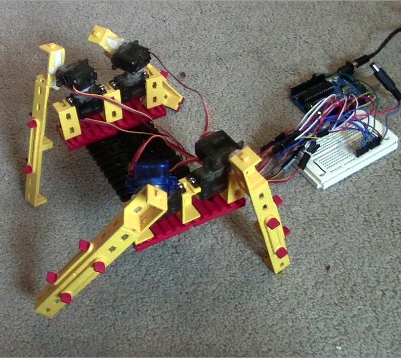
Step 2: Building the Frame
Assuming you have fischertechnik, you can just tell what pieces I’m using to build this. I’m sorry I can’t offer much more of and explanation!
Step 3: Mounting the Servos
Now get out your dremel! The servos conveniently fit between the ‘bricks’. Drill a small pilot hole, then using the screws the servo came with, screw them in. If you don’t want to screw into you pieces, that OK, just use some hot glue, but, it’s always easier disassemble if you use screws. Note: You will want to screw these on BEFORE you put on the arms, or else the arm will be in the way of your screw making it difficult. And why do I know this? I’ll let you guess =) Repeat this on the other side.
Step 4: Mounting the Servos on Servos
You will first need to screw on the circular servo attachment. If the servo is facing away from you, turn it all the way to the right. See pictures.
Now the circular servo arm is different from the other arms; the screw sticks up above the plastic unlike the other ones, which the screw head sinks below the plastic. So, with this bump in the middle, a flat surface cannot be mounted totally flat, instead it will wobble and pivot around the center. To fix this, I’m taking a 7/32 bit (one size smaller than 1/4 on a standard drill set) and drilling a small indent on the servo that will be glued on top of the base servo. See pictures. Then using hot glue, glue the two servos together.
Step 5: Mounting the Spidey Legs!
Step 6: Seeing it all Together
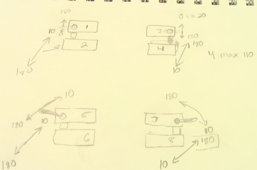
Step 7: Creating a Diagram For Reference
Now, this is the most helpful step of all. Create a diagram like the one shown in the picture, and figure out for each servo which way is 180 deg. and which is 0 deg.. Then number all the servos. These numbers are what you will be using in your Arduino program.
For more detail: Arduino Robotic Spider V8
- What is the main goal of this project?
The main goal is to teach the fundamentals of servos, synchronizing them, programming them, and understanding the range and strength of servos. - How do you mount the servos on the Fischertechnik frame?
You should screw them in using the screws that came with the servo before attaching the arms to avoid obstruction. - Can you use hot glue instead of screws for mounting servos?
Yes, you can use hot glue if you do not want to screw into the pieces, though screws are easier for disassembly. - What is the best way to fix the wobble when mounting a servo on top of another?
You must drill a small indent on the base servo using a 7/32 bit and then use hot glue to secure the two servos together. - How many arm assemblies are needed for the spider?
You will need four of these arm assemblies to complete the mounting process. - Why is creating a diagram helpful in Step 7?
Creating a diagram helps figure out which direction corresponds to 180 degrees and 0 degrees for each servo and allows you to number them for the Arduino program. - What tools are required to drill pilot holes for the servos?
You need a Dremel with a very tiny drill bit that is a little bit smaller than the screws that come with the servo. - Does the project require a specific type of construction toy?
Yes, the project specifically uses Fischertechnik, also referred to as FT.