
Summary of Arduino Real Time Clock Using DS1307
This article explains how to build an Arduino-based clock and calendar using the DS1307 Real-Time Clock (RTC) module. It details the necessary circuit connections, including I2C pull-up resistors, two buttons for setting time/date, an LCD display, and a toggle LED. The guide also outlines the specific steps required to write data to the DS1307 via the I2C protocol, emphasizing the need to consult the datasheet for register addresses and binary addressing.
Parts used in the Arduino Real Time Clock Project:
- Arduino board
- DS1307 Real Time Clock (RTC) chip
- LCD display
- Two push buttons
- LED
- 10K pull-up resistors
This topic shows how to interface Arduino with DS1307 real time clock to make a clock and calender.
To understand the project and code easily you have to read the datasheet of the DS1307.
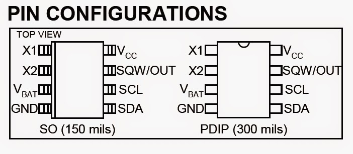
DS1307 Pin assignment:
The picture is taken from ds1307 datasheet and it shows the pin assignment of our chip RTC:
Arduino real time clock using DS1307 circuit:
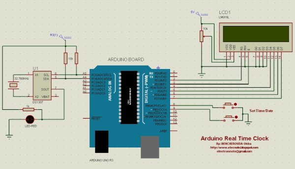
On the circuit schematic there are two buttons used to set the time and date.
The LCD display shows both time and date at the same time, and the LED connected to the ds1307 toggles on and off (can be programmed on the software).
The I2C bus needs pullup resistors to run that why I used the 10K as a pullup resistors.
Arduino real time clock using DS1307 code:
We have to follow the table shown below write/read date to/from ds1307:
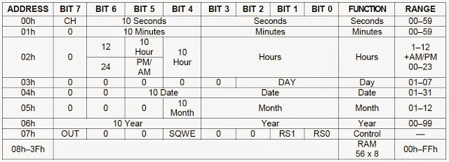
To write data to the ds1307RTC you have to follow these steps:
1 – Start I2C protocol,
2 – Send the DS1307 address which is in binary 11010000 (0x68),
3 – Send register address according to the below table (for example hour register is 0x02),
4 – Write register value,
5 – Stop the I2C protocol.
Writing data to ds1307 Arduino code:
Read More: Arduino Real Time Clock Using DS1307
-
How do you interface Arduino with DS1307?
You must read the DS1307 datasheet to understand the project and code easily. -
Why are 10K resistors used in the circuit?
The I2C bus needs pullup resistors to run, so 10K resistors are used as pullups. -
What components are connected to the DS1307 in this project?
The circuit includes an LCD display, two buttons for setting time and date, and an LED that toggles on and off. -
What is the binary address for the DS1307?
The DS1307 address sent during the I2C protocol is 11010000 (0x68). -
Which register address corresponds to the hour?
The hour register address is 0x02 according to the provided table. -
Can the LED behavior be changed?
Yes, the LED connected to the DS1307 can be programmed to toggle on and off via software. -
What are the steps to write data to the DS1307?
The steps are: start I2C, send the DS1307 address, send the register address, write the register value, and stop the I2C protocol.
