Summary of Arduino-Powered Door Automation with Motion Sensor
This article guides enthusiasts in building an automatic door opener using an Arduino UNO, a servo motor, and an IR sensor. The system detects motion to open the door for two seconds before automatically closing it, with LEDs indicating the door's status. It includes detailed circuit connections, component lists, and code instructions for implementation.
Parts used in the Automatic Door Opener:
- Arduino UNO
- Servo motor
- IR sensor
- Red LED
- Green LED
- 220 ohm resistor
- Jumper wires
- Breadboard
- USB cable
- Cardboard gate
Introduction
Hello enthusiasts, welcome back to Techatronic. Have you ever encountered an automatic door that seamlessly opens and closes on its own? In this guide, we’ll demonstrate how you can craft your very own automatic door opener using a sensor and Arduino UNO. Typically, these types of entrances are commonplace in hotels, metros, offices, etc., and often employ specialized motors for their operation. However, in our project, we’re utilizing a servo motor for this specific purpose. For more insights into IoT and fundamental electronics, explore our collection of articles. Additionally, we offer an Ebook focused on Arduino, featuring over 10 intriguing projects complemented by well-explained code and circuit diagrams. To get started, follow the provided circuit diagram and proceed to upload the code to your Arduino.
Description
Securely attach the servo motor’s rotating shaft to the cardboard gate, ensuring free rotation capability.
Upon entering the IR sensor’s range, the servo motor initiates rotation, automatically opening the door.
After a predefined two-second delay, the door will autonomously close. The code provided can be adjusted to modify the time delay according to your specific needs.
The red LED illuminates upon successful closure of the door, while the green LED signals the impending door opening.
For further exploration, you can examine our creation of a smart dustbin utilizing Arduino and IR sensors.
Components Required
- Arduino UNO
- Servo motor
- IR sensor
- Red and green LEDs
- 220 ohm resistor
- Jumper wires and a breadboard
- USB cable for uploading the code
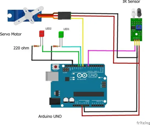
Circuit for Automatic Door Opener With Sensor
Take a servo motor and link its VCC wire to the Arduino’s 5-volt pin. Subsequently, connect its negative wire to the GND pin of the Arduino. Establish a connection between the signal wire of the servo motor and the Arduino’s digital-9 pin.
Connect the VCC pin of the IR sensor module to the Arduino’s 5-volt pin, and link the GND pin of the IR sensor module to the Arduino’s GND pin. Attach the OUT pin of the IR sensor to the digital-7 pin of the Arduino.
Now, acquire two LEDs and connect their negative legs to the GND pin of the Arduino using a 220-ohm resistor. Connect the positive leg of the red LED to the digital-11 pin of the Arduino. Similarly, link the positive pin of the green LED to the digital-10 pin of the Arduino.
Your circuit assembly is now completed, allowing you to proceed with the subsequent steps.
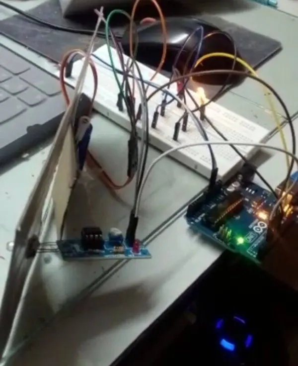
PCBWay PCB Prototyping Services
I’ve completed the circuit assembly on a breadboard. However, I acknowledge that a breadboard setup may not be the most efficient for this project type. That’s why PCBWay provides rapid PCB prototyping services tailored for research endeavors. Personally, I highly recommend PCBWay due to their ability to deliver accurately fabricated boards in just 24 hours on your first attempt!
The prototyping phase stands as a pivotal time for engineers, students, and enthusiasts. PCBWay not only expedites the production of your boards but also ensures accuracy and cost efficiency. This significantly minimizes expenses and accelerates the development timeline for your electronic projects.
PCBWay offers a spectrum of PCBs, ranging from 2 Layer boards to highly advanced HDI and flex boards. Despite the significant differences in functionality and application areas among the PCBs they manufacture, I’m thoroughly impressed with the board quality, delivery speed, and cost-effectiveness.
Code for Automatic Door Opener With Sensor
// Techatronic.com
#include
Servo s1;
int val = 0 ;
void setup()
{
Serial.begin(9600); // sensor buart rate
s1.attach(3);
pinMode(2,INPUT);
pinMode(5,OUTPUT); // led green pin
pinMode(6,OUTPUT); // led red pin
}
void loop()
{
val = digitalRead(2); // IR sensor output pin connected
Serial.println(val); // see the value in serial mpnitor in Arduino IDE
delay(1);
if(val == 1 )
{
digitalWrite(5,HIGH); // LED ON
digitalWrite(6,LOW); // LED OFF
s1.write(90);
delay(2000);
}
else
{
digitalWrite(5,LOW); // LED OFF
digitalWrite(6,HIGH); // LED ON
s1.write(0);
}
}
We trust you found the automatic door opener with a sensor interesting, and we encourage you to attempt building it yourself. Should you encounter any uncertainties regarding this project, please don’t hesitate to ask in the provided comment section. Additionally, explore more articles related to Arduino and Raspberry Pi authored by our team.
- What components are required to build this automatic door?
The project requires an Arduino UNO, servo motor, IR sensor, red and green LEDs, a 220 ohm resistor, jumper wires, a breadboard, and a USB cable. - How does the servo motor operate in this circuit?
The servo motor rotates upon entering the IR sensor's range to open the door and closes after a two-second delay. - Can the time delay for the door closing be changed?
Yes, the provided code can be adjusted to modify the time delay according to specific needs. - Which pin connects the signal wire of the servo motor?
The signal wire of the servo motor connects to digital-9 pin of the Arduino. - What is the function of the red and green LEDs?
The green LED signals the impending door opening, while the red LED illuminates upon successful closure. - How is the IR sensor connected to the Arduino?
The OUT pin of the IR sensor attaches to digital-7 pin, VCC to 5-volt, and GND to GND on the Arduino. - Does the code support serial monitoring?
Yes, the code initializes Serial communication at 9600 baud rate to print sensor values in the Serial Monitor. - What happens when the IR sensor detects an object?
When the sensor value is 1, the green LED turns on, the servo moves to 90 degrees, and waits for two seconds.