Summary of ARDUINO FM RADIO RECEIVER WITH TEA5767 AND A NOKIA 5110 LCD DISPLAY
This article details a DIY Arduino-based FM radio receiver project using the TEA5767 module and an Arduino Nano. It highlights the chip's integrated features like RF amplification, PLL tuning, and stereo decoding, controlled via I2C. The system includes a Nokia 5110 LCD for visual feedback on frequency and signal strength, with potentiometers managing volume and tuning adjustments.
Parts used in the Arduino based FM radio receiver:
- Arduino Nano
- TEA5767 FM radio module
- Nokia 5110 LCD
- Potentiometers
- Headphone jack/speaker
- Antenna
- 32.768 kHz clock crystal (optional)
- 13 MHz crystal (optional)
FM radio transmitters and receivers are one of the projects that fascinated a lot of people and drove them to become makers. The lure of being able to deploy your own radio station, or build your own surveillance(-like) devices was what encouraged most of us to build our first fm transmitter or receiver. Nowadays, microcontrollers help simplify and add a lot of functions to analog projects that’s why for today’s tutorial, we will look on how you can build an Arduino based FM radio receiver using the TEA5767 FM radio and an Arduino Nano.
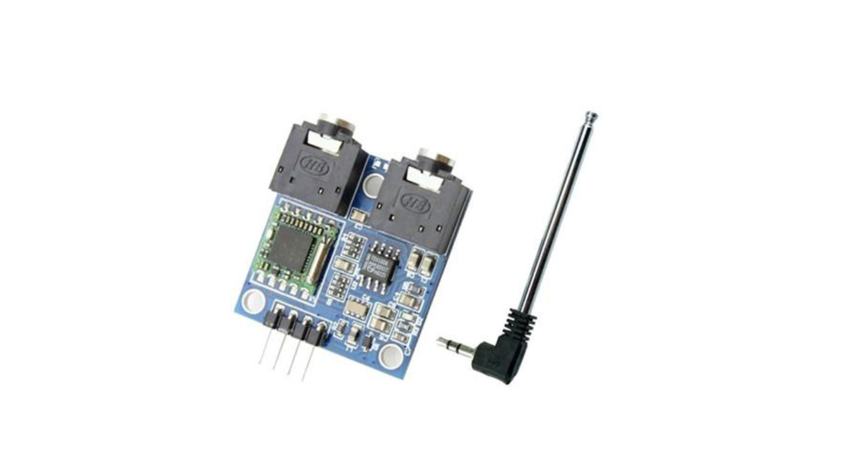
At the heart of today’s project is the cheap TEA5767 FM radio module. This module comes with all the components required to build a FM radio receiver, all on board. The module is based on the TEA5767GH which is a single-chip, electronically tuned, FM stereo radio for low-voltage applications with fully integrated Intermediate Frequency (IF) selectivity and demodulation. Through an I2C interface, the module can be connected to a microcontroller to digitally control its tuning frequency and other characteristics, giving room for opportunities to digitize some of its operations. It comprises of two headphone jacks, one of which is for connection to an headphone/speaker while the other is for connection to the antenna which usually comes with the module.
Some of the features of the TEA5767 chip are outlined below:
- High sensitivity due to integrated low-noise RF input amplifier
- FM mixer for conversion to IF of the US/Europe (87.5 MHz to 108 MHz) and Japanese (76 MHz to 91 MHz) FM band
- Preset tuning to receive Japanese TV audio up to 108 MHz
- RF Automatic Gain Control (AGC) circuit
- LC tuner oscillator operating with low cost fixed chip inductors
- FM IF selectivity performed internally
- No external discriminator needed due to fully integrated FM demodulator
- Crystal reference frequency oscillator; the oscillator operates with a 32.768 kHz clock crystal or with a 13 MHz crystal and with an externally applied 6.5 MHz reference frequency
- Phase-locked loop (PLL) synthesizer tuning system
- I 2C-bus and 3-wire bus, selectable via pin BUSMODE
- 7-bit IF counter output via the bus
- 4-bit level information output via the bus
- Soft mute(Can be switched off via Bus)
- Signal dependent mono to stereo blend
- Stereo Noise Cancelling (SNC)(Can be switched off via Bus)
- Signal dependent High Cut Control (HCC) (can be switched off Via Bus)
- Adjustment-free stereo decoder
- Autonomous search tuning function
- Standby mode
- Two software programmable ports
- Bus enable line to switch the bus input and output lines into 3-state mode
More info on the chip can be found in its datasheet.
For this project, we will connect the FM module to Arduino nano, so we will be able to set its tune frequency, display its signal strength, current frequency, stereo mode and other. The Nokia 5110 LCD will be used as the system’s display, providing visual feedback to the user while potentiometers are used to set the frequency and volume of the radio receiver. Turning the knobs in one direction will increase the volume or increase the frequency (depending on the particular knob being turned) and vice versa.
Read more: ARDUINO FM RADIO RECEIVER WITH TEA5767 AND A NOKIA 5110 LCD DISPLAY
- How does the microcontroller interact with the FM module?
The microcontroller connects to the module through an I2C interface to digitally control tuning frequency and other characteristics. - What display is used in this project?
A Nokia 5110 LCD is used to provide visual feedback regarding signal strength, current frequency, and stereo mode. - Can the TEA5767 chip operate without external discriminators?
Yes, it has a fully integrated FM demodulator so no external discriminator is needed. - What functions do the potentiometers serve?
Potentiometers are used to set the frequency and volume of the radio receiver by turning knobs in specific directions. - Does the TEA5767 support both mono and stereo modes?
Yes, it features signal-dependent mono to stereo blend and an adjustment-free stereo decoder. - How can users search for stations automatically?
The chip includes an autonomous search tuning function that can be utilized by the system. - What frequency bands does the TEA5767 cover?
It covers the US/Europe band from 87.5 MHz to 108 MHz and the Japanese band from 76 MHz to 91 MHz. - Is there a way to reduce noise during reception?
The module includes Stereo Noise Cancelling which can be switched off via the bus if desired.