Summary of Arduino Based RGB Colour Code Generator
This article describes an Arduino-based RGB colour code generator circuit. It uses an Arduino Uno, three potentiometers, an RGB LED, and a 16×2 LCD to visualize colour mixing. By adjusting the potentiometers, users control the intensity of red, green, and blue light. The system converts analogue inputs to digital values, calculates PWM duty cycles, and displays both decimal and hexadecimal colour codes on the LCD screen for web design learning purposes.
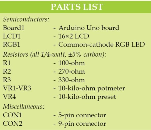
Parts used in the RGB Colour Code Generator:
- Arduino Uno board
- 16×2 LCD (wired in 4-bit mode)
- RGB LED
- Potentiometers VR1, VR2, and VR3
- Resistors R1, R2, and R3
- External 9V, 500mA adaptor or USB cable
- 220-ohm resistor for LCD backlight
- Single-side PCB with connectors CON1 and CON2
 Red, green and blue (RGB) are the basic colours for generatingvarious other colours by mixing colours in a particular proportion. This technique is used in TVs, mobiles etc. Similarly, Web designing using HTML or any other language requires the hex code of a particular colour in the design. Presented here is the circuit for learning the concept of RGB colour code generator and the respective hex codes of those colours.
Circuit and working for RGB Colour Code Generator
Circuit diagram of the RGB colour code generator is shown in Fig. 1. It is built around Arduino Uno board (Board1), 16×2 LCD (LCD1), RGB LED (RGB1) and a few other components.
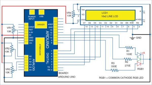
Circuit of the RGB colour code generator
Arduino board is the brain of the circuit that performs colour generation using pulse width modulation (PWM). Three potentiometers control intensity of the RGB LED. The 16×2 LCD wired in 4-bit mode is used to display the value of each colour in the first row and the hex value in the second row.
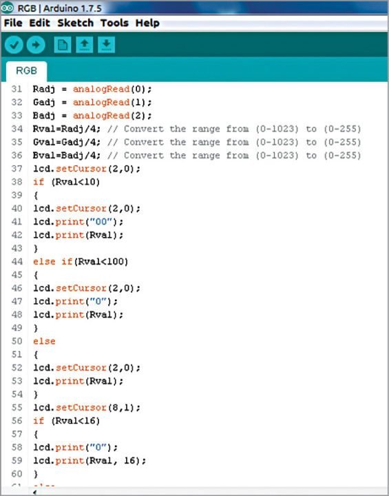
Screenshot of the source code
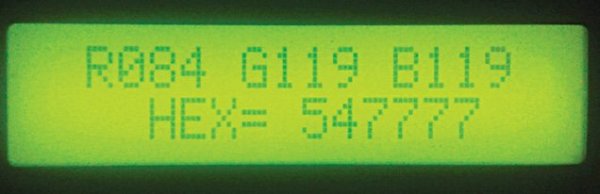
RGB colour display on the LCD
Intensity of each colour is controlled by potmeters VR1, VR2 and VR3. These are connected to analogue inputs A0, A1 and A2 of Arduino board. The program continuously scans the analogue input of the board. The analogue-to-digital converter (ADC) of Arduino converts the analogue value into a 10-bit digital value. Since resolution of the PWM module of the board is 8-bit, the 10-bit analogue value is converted into 8-bit value by the program. Screenshot of the source program is shown in Fig. 2.
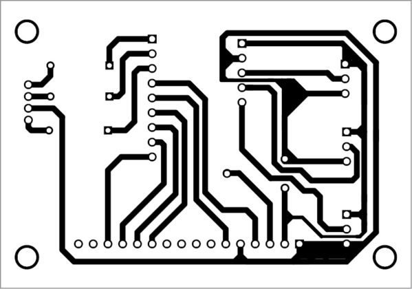
PCB pattern of the RGB colour code generator
Thus, the 8-bit value controls the duty cycle of the PWM, thereby controlling the intensity of the colour. The RGB LED emits the light of a colour, which is controlled by the potmeters (VR1 through VR3). The corresponding colour value is displayed in the first row as Rxxx Gxxx Bxxx, where xxx are the numbers for RGB colours, respectively. The second line displays the hex value of the colour as HEXxxxxxx. RGB colours with numbers are displayed on the LCD as shown in Fig. 3.
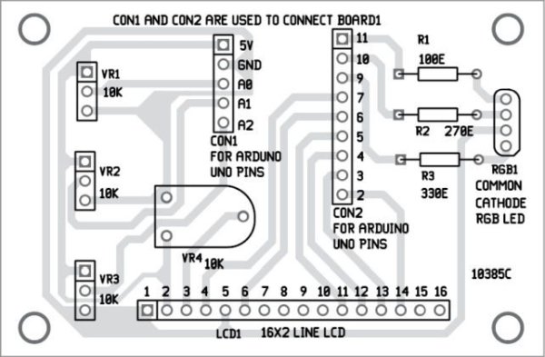
Component layout of the PCB
Resistor values (R1, R2 and R3) are critical. Choose these values after calibration. For calibration, connect each lead of the RGB LED in series with a 1-kilo-ohm potmeter to 5V. Vary the potmeter to low-resistance side until the RGB LED emits a slightly whitish colour. Measure resistance from the arm of the potmeter to the anode of the LED and note down the resistance value, say, 100-ohm. Using the same technique, measure the remaining two leads of the LED. These resistance values were found to be 270-ohm and 330-ohm, respectively, during testing.
Be careful while calibrating as there is a chance of burning the potmeter when the arm moves to very low-resistance side due to more current passing through the arm.
Construction and testing
An actual-size, single-side PCB for the RGB colour code generator is shown in Fig. 4 and its component layout in Fig. 5. Assemble the circuit on a designed PCB. Connectors CON1 and CON2 in the PCB layout are used to connect Board1 (Arduino UNO board) through external connectors. Arduino board can be powered by an external 9V, 500mA adaptor or USB cable.
Software for the RGB generator is written in Arduino programming language. Arduino UNO is programmed using Arduino IDE. Select the correct board from Board Tools menu in Arduino IDE, select COM port and upload the program (RGB.ino) through the standard USB port in computer.
Note. For backlight, connect pin 15 of LCD1 to +5V via a 220-ohm resistor and pin 16 to GND.
Download PCB and Component Layout PDFs: click here
Download source code
Read More Detail:Arduino Based RGB Colour Code Generator
- How does the circuit generate different colours?
The circuit uses pulse width modulation to control the intensity of the RGB LED via three potentiometers connected to analogue inputs. - What is the function of the 16×2 LCD in this project?
The LCD displays the decimal value of each colour in the first row and the corresponding hex value in the second row. - How are the analogue values converted for the PWM module?
The 10-bit analogue-to-digital converter output is converted into an 8-bit value by the program to control the PWM duty cycle. - Can I power the Arduino board using a battery?
The text states the board can be powered by an external 9V, 500mA adaptor or a USB cable. - How do I calibrate the resistors R1, R2, and R3?
Connect each lead in series with a 1-kilo-ohm potmeter to 5V, vary it until the LED emits a slightly whitish colour, and measure the resistance. - What happens if the potmeter arm moves to the very low-resistance side?
There is a chance of burning the potmeter due to more current passing through the arm during calibration. - Which software is required to program the Arduino UNO?
The software for the generator is written in the Arduino programming language and uploaded using the Arduino IDE. - How should the LCD backlight be connected?
Pin 15 of the LCD must be connected to +5V via a 220-ohm resistor, and pin 16 must be connected to GND.