Summary of Arduino Based Piano with Recording and Replay
This article outlines building a compact Arduino piano featuring eight push buttons, a buzzer, and an LCD display. The project utilizes the Arduino's tone() function to generate musical notes and includes a unique recording capability to capture and replay tunes. By employing a potential divider circuit on a single analog pin, the design efficiently interfaces multiple inputs without consuming excessive microcontroller pins.
Parts used in the Arduino Piano:
- Arduino Uno
- 16*2 LCD Display
- Buzzer
- Trimmer 10k
- SPDT switch
- Push button (8 Nos)
- Resistors (10k, 560R, 1.5k, 2.6k, 3.9k, 5.6k, 6.8k, 8.2k, 10k)
- Breadboard
- Connecting wires
Arduino has been a boon for people who are not from the electronics background to build stuff easily. It has been a great prototyping tool or to try something cool, in this project we are going to build a small yet fun Piano using the Arduino. This piano is pretty much plain with just 8 push buttons and buzzer. It uses the tone() function of Arduino to create various types of piano notes on the speaker. To spice it up a bit we have added the recording feature in the project, this enables us to play a tune record it and play it again repeatedly when required. Sound interesting right!! So lets’ get building….
Materials Required:
- Arduino Uno
- 16*2 LCD Display
- Buzzer
- Trimmer 10k
- SPDT switch
- Push button (8 Nos)
- Resistors (10k, 560R, 1.5k, 2.6k, 3.9, 5.6k, 6.8k, 8.2k, 10k)
- Breadboard
- Connecting wires
Circuit Diagram:
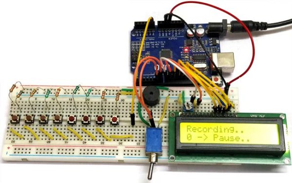
The complete Arduino Piano Project can be built on top of a breadboard with some connecting wires. The circuit diagram made using fritzing that shows the breadboard view of the project is shown below
Just follow the circuit diagram and connect the wires accordingly, the push buttons and buzzer as used with a PCB module but in actual hardware we have used only the switch and buzzer, it should not confuse you much because they have the same type of pin out. You can also refer to the below image of the hardware to make your connections.
The value of the resistors from the left is in the following order, 10k, 560R, 1.5k, 2.6k, 3.9, 5.6k, 6.8k, 8.2k and 10k. If you do not have the same DPST switch you can use normal toggle switch like the one shown in the circuit diagram above. Now let’s look into the schematics of the project to understand why we have made the following connections.
Schematics and Explanation:
The schematics for the circuit diagram that is shown above is given below, it was also made using Fritzing.
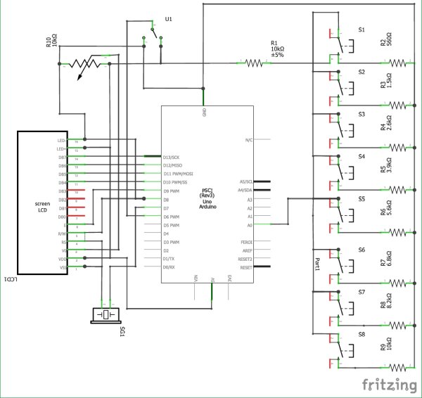
One main connection that we have to understand is that how we have connected the 8 push buttons to the Arduino through the Analog A0 pin. Basically we need 8 input pins which can be connected to the 8 input push buttons, but for projects like this we cannot use 8 pins of the microcontroller just for push buttons since we might need them for later use. In our case we have the LCD display to be interfaced.
So we use the analog pin of the Arduino and form a potential divider with varying resistor values to complete the circuit. This way when each button is pressed a different analog voltage will be supplied to the Analog pin. A sample circuit with only two resistors and two push buttons are shown below.
Read more: Arduino Based Piano with Recording and Replay
- What is the main purpose of this project?
To build a small yet fun piano using Arduino that can record and replay tunes. - How does the piano create different musical notes?
It uses the tone() function of Arduino to create various types of piano notes on the speaker. - Why are only eight push buttons used instead of more?
The project uses just eight push buttons and a buzzer for a plain but functional design. - How do we connect eight buttons without using eight input pins?
We use the analog pin A0 with a potential divider to supply different voltages for each button press. - Can I use a normal toggle switch if I do not have an SPDT switch?
Yes, you can use a normal toggle switch like the one shown in the circuit diagram. - What tool was used to make the circuit diagrams?
The circuit diagrams were made using Fritzing. - Does the hardware setup differ significantly from the PCB module shown?
No, the actual hardware uses only the switch and buzzer which have the same type of pin out. - Which resistor values are listed in order from left to right?
The order is 10k, 560R, 1.5k, 2.6k, 3.9, 5.6k, 6.8k, 8.2k and 10k.