Summary of Arduino and Xbee wireless setup
This article explains how to use the Arduino Wireless shield with an XBee 802.15.4 module for Zigbee communication. It details a basic setup where two Arduino boards exchange serial data without configuration, demonstrating LED control via 'H' and 'L' commands using the Physical Pixel sketch at 9600 baud.
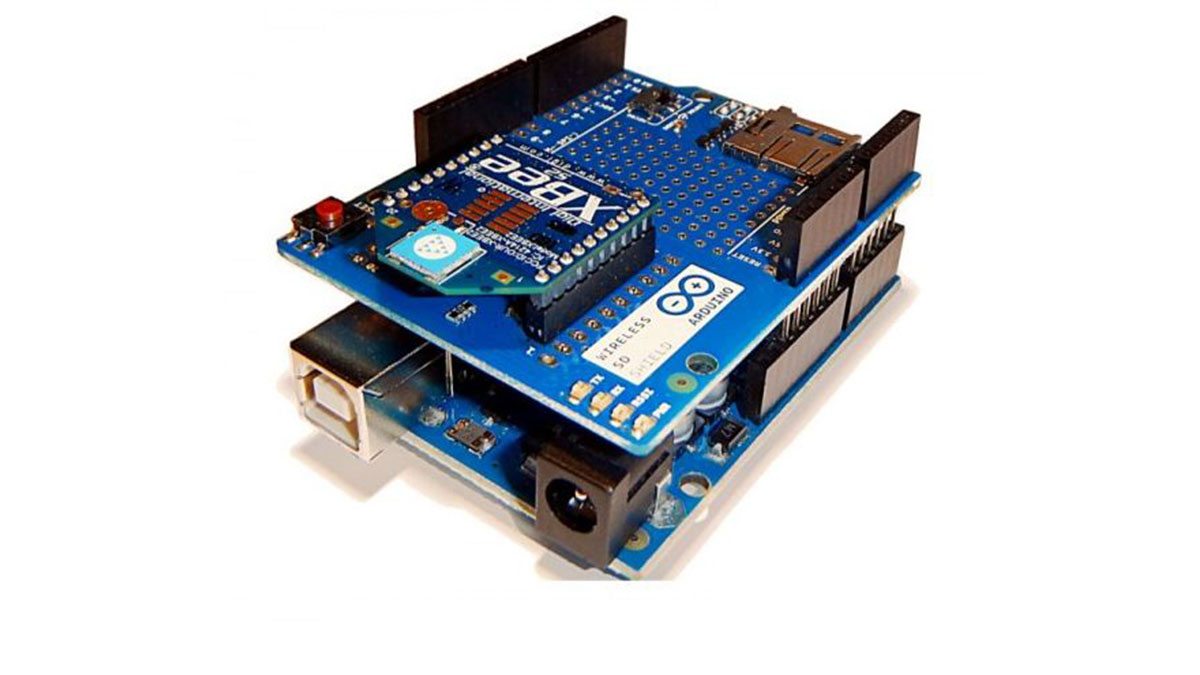
Parts used in the Arduino Wireless Shield Project:
- Arduino board
- Arduino Wireless shield
- XBee 802.15.4 module (Series 1)
- LED attached to pin 13
- Arduino serial monitor
- Physical Pixel sketch
The Arduino Wireless shield allows your Arduino board to communicate wirelessly using Zigbee. This documentation describes the use of the shield with the XBee 802.15.4 module (sometimes called “Series 1” to distinguish them from the Series 2 modules, although “Series 1” doesn’t appear in the official name or product description).
A Simple Example
You should be able to get two Arduino boards with Wireless shields talking to each other without any configuration, using just the standard Arduino serial commands (described in the reference).
To upload a sketch to an Arduino board with a Wireless shield, remove the Xbee. Then, you can upload a sketch normally from the Arduino environment. In this case, upload the Communication | Physical Pixel sketch to one of the boards. This sketch instructs the board to turn on the LED attached to pin 13 whenever it receives an ‘H’ over its serial connection, and turn the LED off when it gets an ‘L’. You can test it by connecting to the board with the Arduino serial monitor (be sure it’s set at 9600 baud), typing an H, and pressing enter (or clicking send). The LED should turn on. Send an L and the LED should turn off. If nothing happens, you may have an Arduino board that doesn’t have a built-in LED on pin 13 (see theboard index to check for sure), in this case you’ll need to supply your own.
For more detail: Arduino and Xbee wireless setup
- How do I upload a sketch to an Arduino board with a Wireless shield?
You must remove the Xbee module before uploading the sketch normally from the Arduino environment. - What does the Physical Pixel sketch do?
This sketch turns on an LED connected to pin 13 when it receives an H and turns it off when it receives an L. - At what baud rate should I set the Arduino serial monitor?
The serial monitor must be set to 9600 baud to test the sketch correctly. - Can I get two Arduino boards with Wireless shields talking to each other without any configuration?
Yes, you can communicate between them using standard Arduino serial commands without configuration. - What should I do if my board does not have a built-in LED on pin 13?
You will need to supply your own external LED if the board lacks a built-in one on that pin. - Which XBee module is compatible with this documentation?
The documentation describes using the XBee 802.15.4 module, sometimes referred to as Series 1.