Summary of Arduino Alphabet
This project demonstrates generating the English alphabet (A-Z) using an Arduino Uno and a common cathode alphanumeric display. The system utilizes a custom Photo shield PCB, 14-segment display, and specific resistors to visualize each letter sequentially. The assembly involves soldering components onto the board, cutting header pins for precise connections, and interfacing with the Arduino hardware via designated digital and analog pins.
Parts used in the Arduino Alphabet Project:
- Photo shield for Arduino Uno (PCB only)
- Common cathode alphanumeric display (14 segments)
- 14 Resistors of 220 Ohm, 1/4 Watt
- Header pin male of 1x40 pins
- Arduino Uno
- USB-A to USB-B cable of 3ft
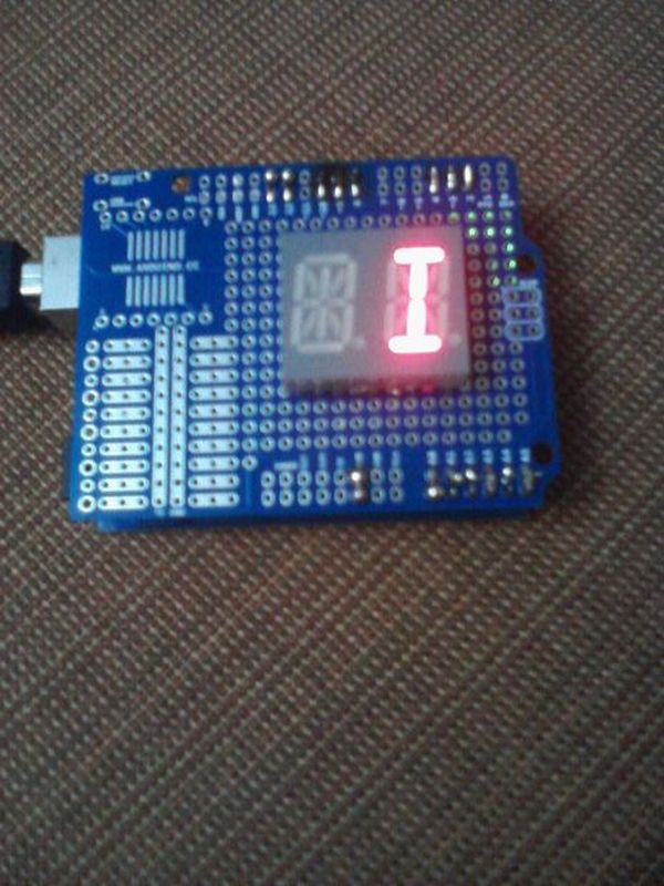
This project is very interesting because it shows the sequence of all letters of our English alphabet. That is, the project generates capital letters from the A to the Z based on Arduino code and showed by an alphanumeric display. I’m using a common cathode alphanumeric display and an Arduino Uno in order to constructing this project. Use the following link so that watch a video of the project working: http://www.youtube.com/watch?v=jmZ5V43CFf8
Step 1: Bill of Materials
Major Components in Project
1 Photo shield for Arduino Uno (PCB only)
1 Common cathode alphanumeric display (14 segments)
14 Resistors of 220 Ohm, 1/4 Watt
1 Header pin male of 1×40 pins
1 Arduino Uno
1 USB-A to USB-B cable of 3ft
Required tools and supplies:
Soldering iron:
Jumper wire
Needle nose pliers
Wire stripper
Multimeter
Step 2: Project’s Diagram
Firstly, you should check what you are going to do then observe the diagram of your project.
Step 3: Install the Alphanumeric Display
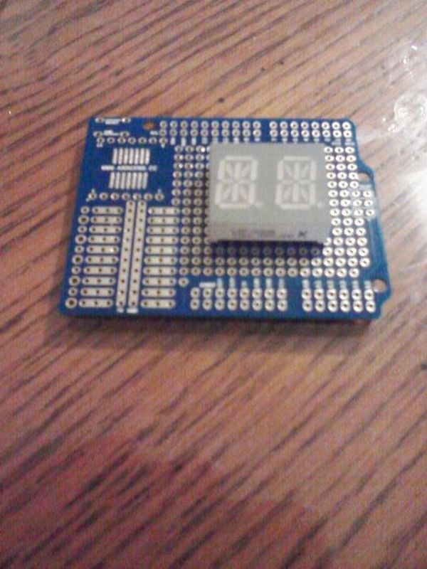
Observing your diagram, install the alphanumeric display on the PCB and solder its pins on it.
Step 4: Install the Resistors of 220 Ohm
After installing the alphanumeric display, install the resistors of 220 Ohm among the alphanumeric display and the pins marked in the project’s diagram. Note that I first connected the resistors and then the pins to interface to my Arduino hardware. However, being better that you first install the pins and then the resistors because it’s easier for doing all connections and solder to the pins.
Step 5: Separate the Pins that You Will Need
Take the component 1×40 header pins male and then cut 1×15 pins so that you can later separate those 15 pins in 1×3, 1×3, 1×6, and 1×1 pin that are the pins that you will need to connect to your Arduino platform.
Step 6: Insert the Pins Reserved
Insert the pins reserved in your Arduino hardware Note the pins are 1×6 ( A0, A1, A2, A2, A3, A4, A5), 1X3 (2, 3, 4), 1X3 (8, 9, 10), 1X2 (12, 13), and 1×1 (GND).
For more detail: Arduino Alphabet
- What components are required to construct this project?
The project requires a photo shield, common cathode alphanumeric display, 14 resistors of 220 Ohm, a 1x40 male header pin, an Arduino Uno, and a 3ft USB cable. - How do you connect the resistors in the assembly process?
You install the 220 Ohm resistors between the alphanumeric display and the marked pins on the diagram. - Can I use any type of alphanumeric display for this project?
No, the article specifies using a common cathode alphanumeric display with 14 segments. - What is the best way to cut the header pins for connection?
You should cut 15 pins from the 1x40 header and separate them into groups of 1x3, 1x3, 1x6, and 1x1. - Which pins are reserved for connecting to the Arduino platform?
The reserved pins include A0 through A5, digital pins 2, 3, 4, 8, 9, 10, 12, 13, and GND. - Does the project generate lowercase letters or capital letters?
The project generates capital letters from A to Z based on the Arduino code. - What tools are needed to assemble the circuit?
You need a soldering iron, jumper wires, needle nose pliers, a wire stripper, and a multimeter.