Summary of Arduino 4 led madness
This project demonstrates wiring four LEDs to an Arduino Duemilanove to flash them ten times, ideal for beginners. It involves placing LEDs and resistors on a breadboard, connecting grounds and positive leads to specific pins (13, 12, 11, 10), and utilizing the built-in resistor on pin 13.
Parts used in the Arduino 4 LED Flash Project:
- Arduino Duemilanove
- Breadboard
- 4 LEDs
- 10-15 jumper wires
- 3 resistors
In this instructables you will learn how to wire 4 LED’S and make them flash 10 times. This is a great Starter project!!
what you will need…
1: arduino (I am using an Duemilanove)
1: breadboard
4: LED’s
10-15: jumper wires
3: resistors
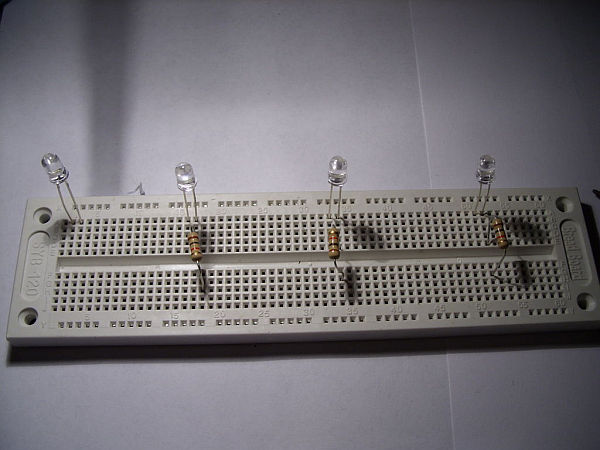
Step 1: Adding the LED’s and Resistors1
First put the LED’s on the breadboard.
Make Sure the long lead is to the left as seen i the picture!
Next add the Resistors to the last 3 LED’s,
place in the long lead.
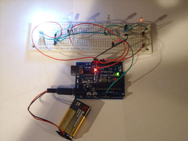
Step 2: Wiring this to the Arduino!
First the ground, wire 2 grounds to the breadboard like in the picture.
Next going to each led, take 4 more led’s and go from the 2 grounds to each short lead.
Step 3: Wiring the positive leads!
For this code you will be using pins 13,12,11,10
pin 13 has a built in resistor so that is why you don’t need to use a resistor.
start with pin 13 and wire it to the first LED.
Then Just go do the line and wire the rest of the LED’s using pins 12,11,10
For more detail: Arduino 4 led madness
- How many times do the LEDs flash?
The LEDs are programmed to flash 10 times. - Which Arduino model is used in this guide?
An Arduino Duemilanove is used. - What happens if I connect the long lead incorrectly?
The instructions specify ensuring the long lead is to the left when placing LEDs on the breadboard. - Why is only one resistor needed for the first LED?
Pin 13 has a built-in resistor, so no external resistor is required for that specific LED. - Which pins control the LEDs in this code?
Pins 13, 12, 11, and 10 are used to wire the positive leads of the LEDs. - How many grounds are wired to the breadboard?
Two grounds are wired to the breadboard. - Where should the resistors be placed?
Resistors are added to the last three LEDs, placed in the long lead. - Is this project suitable for beginners?
Yes, it is described as a great Starter project.