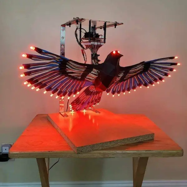
Hello everyone, welcome back to Techatronic. Today, we’re diving into an exciting project centered around illuminating effects. You might have come across RGB and pixel lighting in various settings such as decorations, vehicles, and even light bulbs. Our focus today is on working with WS2811 in conjunction with Arduino Bluetooth control using an Android app. We’ll provide you with all the necessary steps to set this up. Specifically, we’ll be creating an Android app utilizing the MIT App Inventor to control both the color and patterns of the lights. If you’re interested in recreating this project, stay tuned, follow along, and we’ll guide you through each step.
Introduction
The WS2811 IC facilitates addressable RGB lighting, allowing for easy programming with a wide array of effects. I’ve engaged in numerous projects involving WS2811 pixel lights, commonly employed in home, shop, restaurant, and bar decorations. Now, I aim to simplify the control of WS2811 using Arduino through mobile phones. To accomplish this, we’ll leverage the MIT App Inventor. This project involves two primary steps: developing the Android app and handling the circuitry and coding. Let’s commence with the initial phase – creating WS2811 control via Arduino using an Android app. Additionally, I’ve previously utilized this same Android app in various projects, such as controlling a Bluetooth-enabled RC car.
Create an android application.
Today, we’ll guide you through creating an Android app utilizing the MIT App Inventor. This app will leverage the phone’s Bluetooth capability to transmit characters. The app will feature buttons; upon tapping a button, it will transmit specific data to the Arduino. Essentially, it’s an application designed for Bluetooth control. Let’s dive into the step-by-step process of crafting this application.
Step 1
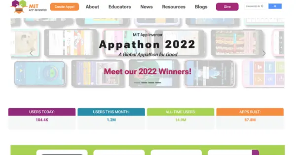
Visit the official MIT App Inventor website and proceed to create your account. Click on the ‘Create App’ button, where you’ll find the choice to either create a new account or log in using your Google account.
step 2.
Sure, here’s a rephrased version:
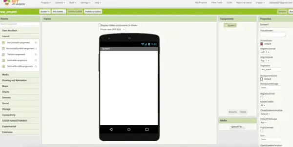
1. “Begin by initiating a new project and naming it accordingly.
2. You’ll find a dashboard for creating the application interface.
3. Within the layout section on the left-hand side, drag and drop the horizontal arrangement onto the mobile screen.”
step 3.
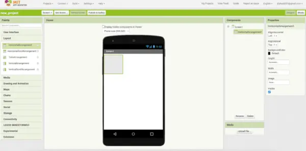
To adjust the width, click on the right side and choose ‘fill parent’. Next, navigate to the user interface section and place the button onto the mobile screen within the horizontal arrangement. Drag and drop at least three buttons into this area.
Step 4.
Modify the properties of the buttons, such as color and name, from the right sidebar.
Move the Bluetoothclient 1 element from the connectivity section to the mobile screen using drag and drop functionality.

Step 5.
Sure, here are the rephrased instructions for two different blocks in an app interface:
1. Locate and select the ‘block button’ situated in the upper right-hand corner, then proceed to commence the coding process.”
2. “Create two distinct blocks within the interface: one for control and another for Bluetooth functionality. These blocks should encompass ‘list picker 1’ and ‘Bluetooth’ respectively.
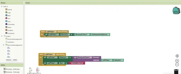
Step 6.
make 3 more blocks as given in the image from control, bluetoothclient1 and text.
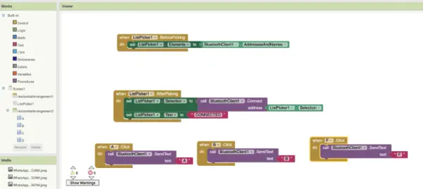
Once your application is prepared, proceed by clicking the ‘Design’ button, followed by ‘Build’ and select ‘Android App.’ The website will display a QR code, which plays a crucial role in controlling RGB with Arduino for your project.
Download ‘MIT App Inventor’ from the Google Play Store onto your mobile device. Scan the identical QR code to automatically download the app onto your phone.
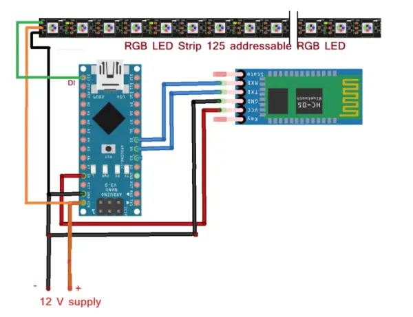
Next, we move on to the second phase of this project: establishing the circuit, which is a straightforward process.
WS2811 Arduino Circuit diagram Bluetooth control using Android app
PCBWay PCB Prototyping Services
I’ve set up the entire circuit on a breadboard, but as you’re aware, using a breadboard isn’t the most efficient approach for this project. That’s where PCBWay’s Rapid PCB Prototyping for Research Work comes in. Personally, I highly recommend PCBWay because they can provide your initial boards within just 24 hours, ensuring you get it right on your first attempt!
The prototyping phase stands as a pivotal time for engineers, students, and hobbyists alike. PCBWay not only accelerates the production of your boards but also ensures precision and cost efficiency. This significantly diminishes expenses and expedites the electronic development process.
PCBWay offers a spectrum of PCBs ranging from 2 Layer PCBs to sophisticated HDI and flex boards. Despite the diverse functionalities and application areas of the produced PCBs, I’m genuinely impressed by the board quality, prompt delivery, and the cost-effectiveness they offer.
WS2811 with Arduino code Bluetooth control using Android app
#include
#define LED_PINA 13
#include
SoftwareSerial mySerial(4, 5); // RX, TX
#define NUM_LEDS 100
CRGB leds[NUM_LEDS];
void setup() {
FastLED.addLeds<WS2812, LED_PINA, GRB>(leds, NUM_LEDS);
mySerial.begin(9600);
Serial.begin(9600);
}
void loop() {
// put your main code here, to run repeatedly:
int q;
if(mySerial.available()>0)
{
char m = mySerial.read();
Serial.println(m);
// Serial.println(t);
switch (m)
{
// warm slowly pattern start here (RED)
case ‘A’:
while(1)
{
if(mySerial.available()>0)
{
break; }
for(q=0; q<=90; q++){ if(mySerial.available()>0)
{
break; }
for ( i = 0; i <=NUM_LEDS; i++ ) { leds[i] = CRGB ( 255,0, 0); if(mySerial.available()>0)
{
break; }}
FastLED.setBrightness( q);
FastLED.show();
delay(d);
if(mySerial.available()>0)
{
break; }
}
for(q=90; q>=0; q–){
if(mySerial.available()>0)
{
break; }
for ( i = 0; i <=NUM_LEDS; i++ ) { leds[i] = CRGB ( 255,0, 0); if(mySerial.available()>0)
{
break; }}
FastLED.setBrightness( q);
FastLED.show();
delay(d);
if(mySerial.available()>0)
{
break; }
}
if(mySerial.available()>0)
{
break; }
}
// warm slowly pattern end here (RED)
// warm slowly pattern start here (BLUE)
case ‘B’:
while(1)
{
for(q=0; q<=90; q++){
for ( i = 0; i <=NUM_LEDS; i++ ) { leds[i] = CRGB ( 0,255, 0); } FastLED.setBrightness( q); FastLED.show(); delay(d); } for(q=90; q>=0; q–){
for ( i = 0; i <=NUM_LEDS; i++ )
{
leds[i] = CRGB ( 0,255, 0);
}
FastLED.setBrightness( q);
FastLED.show();
delay(d);
}
}
If you encounter any challenges, refer to our previous article on uploading code to Arduino. With this information, you should be able to independently create your own system to control WS2811 using an Android app. If you encounter any difficulties, feel free to ask for assistance in the comments section.