Summary of AC Dimmer Circuit: 46
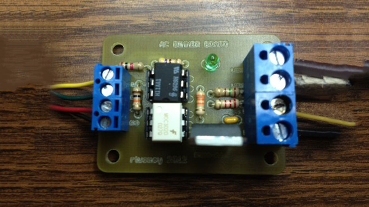
This project is an Arduino-controlled AC dimmer that uses an H11AA1 zero-cross optocoupler for AC phase detection and a MOC3020 plus a power TRIAC (BTA12-600) to chop AC for dimming. The on-board LED mirrors the AC dimming and requires AC zero-cross input to fade correctly. The build includes PCB population and testing instructions, resistor and component placement order, and alternative SSR options for switching.
Parts used in the AC Dimmer Project:
- 33K resistor (R1)
- 10K resistor (R2)
- 1K resistor (R3)
- 470 ohm resistor (R4)
- 180 ohm resistor (R5)
- 2.4K resistor (R6)
- 0.01uF capacitor
- generic LED
- H11AA1 optocoupler (AC input, 1 channel)
- MOC3020 optoisolator triac driver
- BTA12-600 snubberless TRIAC (or equivalent TRIAC)
- Screw terminals (short and tall)
- 6-pin DIP sockets
Green wire is zero_cross signal, goes to Arduino digital pin 2 in.
Yellow wire is light dimming signal, comes from Arduino digital pin 11.
The LED on board should dim or fade along with the AC light source. Fading will not work until AC power is connected, it depends on the zero-cross info from the H11AA1 chip.
Code
- example with slow on/off fade:
- example with potentiometer control:
Diagram
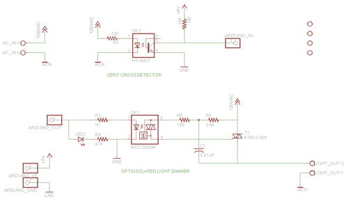 |
| Click for full-size image |
Eagle Files
Parts
- 33K
- 10K
- 1K
- 470
- 180
- 2.4K
- 0.01uF capacitor
- generic LED
- H11AA1 – Optocoupler AC Input 1 Channel http://www.jameco.com/webapp/wcs/stores/servlet/Product_10001_10001_18825_-1
- MOC3020 – DIP-6 OPTOISOLATOR Triac Driver http://www.jameco.com/webapp/wcs/stores/servlet/Product_10001_10001_277780_-1
- BTA12-600 – 600 V, 12 A, SNUBBERLESS TRIAC http://www.jameco.com/webapp/wcs/stores/servlet/Product_10001_10001_2034010_-1
Notes
- Make sure your Triac (T1, BTA12-600) is rated at high enough current for the device you are controlling. The product linked above is rated at 12Amps RMS. That’s a lot of current!
- Alternative TRIACs with different power ratings:
- TIC201M Thyristor TRIAC 600 Volt 12A 3-Pin (2.5A RMS) – http://www.jameco.com/webapp/wcs/stores/servlet/Product_10001_10001_1165690_-1
- Q4008L4 TRIAC 400V (8.0A RMS) – http://www.jameco.com/webapp/wcs/stores/servlet/Product_10001_10001_160207_-1
- Q6008L5 TRIAC 600V (8.0A RMS) – http://www.jameco.com/webapp/wcs/stores/servlet/Product_10001_10001_160215_-1
- Q6015L5 TRIAC 600 V (15A RMS) – http://www.jameco.com/webapp/wcs/stores/servlet/Product_10001_10001_160231_-1
Building from Fabricated PCB
Populate a freshly Fabricated PCB
- Grab your part. Use the parts list
- We are going to build this board from the bottom up, shortest to tallest components.
- Start with the resistors. Get these from the resistor bin.
- 33K (R1)
- 10K (R2)
- 1K (R3)
- 470 (R4)
- 180 (R5)
- 2.4K (R6)
- Insert the resistors into the board in the appropriately labelled spot. You may want to bend the legs slightly to hold them in place.
- Flip the board over and solder each resistor in place. As you solder a resistor, straighten the legs back out. This will give them each solder pad a straight, centered solder blob.
- Make sure that the resistor stays flush to the top side of the board! If one has slipped out, you can reheat the solder pad and push it into place, letting the solder harden again
- Solder joints should be symmetric, conical, and have a shiny finish. You do not want a big ball of solder.
- Clip the resistor leads near the board, at the top of the solder joint. You can do this as you work your way through soldering the resistors, to free up space, or do it all at the end.
- Next, solder the 6-pin DIP sockets in place. These are the next tallest components.
- Make sure that the notch in the DIP socket aligns with the notch in the silkscreen image. This is how you are sure to put the component in correctly. (PIC)
- Find a way to secure them flush to the board while you solder on the back. I just make sure the board is balanced on top of them and apply a little downward force.
- Solder one corner of the socket, then the opposite corner.
- If the socket is not flush. Heat the appropriate corner and push to make it flush, then let the solder harden again.
- When you are satisfied with the flush-mounted DIP socket. Solder the remaining 4 pins.
- Solder the LED.
- Solder the capacitor.
- Solder the short Screw Terminals.
- Solder the tall Screw Terminals.
- Solder the TRIAC.
- Test and verify.
Test and Verify a Soldered Circuit
Other Notes
- How it works. This is a AC chopping circuit, depending on where it cuts the AC waveform the bulb gets more or less current flow:(from digikey http://www.digikey.com/ca/en/techzone/lighting/resources/articles/Retrofit-LED-Bulbs-and-Drivers.html)
Alternative Design
Alternative SSR instead of MOC/Triac combination:
- SSR 120VAC .6A TRIAC 8-DIP – http://search.digikey.com/scripts/DkSearch/dksus.dll?Detail&name=425-2361-5-ND $1.17
- SSR 120VAC .9A TRIAC 8-DIP – http://sharp-world.com/products/device/lineup/data/pdf/datasheet/pr29mf11_e.pdf $1.44
- SSR 120VAC 3A TRIAC 4-SIP – http://search.digikey.com/scripts/DkSearch/dksus.dll?Detail&name=425-2386-5-ND $5
- SSR 120VAC 8A TRIAC 4-SIP – http://search.digikey.com/scripts/DkSearch/dksus.dll?Detail&name=425-2395-5-ND $4.13
- SSR 120VAC 12A TRIAC 4-SIP – http://search.digikey.com/scripts/DkSearch/dksus.dll?Detail&name=425-2397-5-ND
- SSR 120VAC 16A TRIAC 4-SIP – http://search.digikey.com/scripts/DkSearch/dksus.dll?Detail&name=425-2398-5-ND
AC Phase Control (that’s what we are doing):
http://arduino.cc/playground/Code/ACPhaseControl
For more detail: AC Dimmer Circuit: 46
- What is the green wire used for?
The green wire is the zero_cross signal and goes to Arduino digital pin 2. - What is the yellow wire used for?
The yellow wire is the light dimming signal and comes from Arduino digital pin 11. - Will the on-board LED dim without AC power?
No. Fading will not work until AC power is connected because it depends on zero-cross information from the H11AA1 chip. - Which optocoupler provides the zero-cross signal?
The H11AA1 optocoupler provides the zero-cross signal. - Which component drives the TRIAC gate?
The MOC3020 optoisolator triac driver is used to drive the TRIAC gate. - What TRIAC is recommended in the project?
The BTA12-600 snubberless TRIAC rated at 600 V, 12 A is recommended but alternatives with different ratings are listed. - How should components be populated on the PCB?
Populate from shortest to tallest: resistors first (33K, 10K, 1K, 470, 180, 2.4K), then DIP sockets, LED, capacitor, screw terminals, and TRIAC. - What should you verify after soldering?
Test and verify the soldered circuit and ensure solder joints are symmetric and components are flush to the board. - Are there alternative designs to MOC/Triac combination?
Yes. The article lists SSR alternatives with various current ratings as an alternative to the MOC/Triac combination.