In my first Instructable Motion Activated Automatic LED Stair Lights with Arduino I mentioned the use of “Cooperative Multitasking”. So what is it and why is it helpful?
This Instructable attempts to answer the “what is it” and “why is it helpful” question with a simple example that step by step builds up into a more complex example. The end result will hopefully answer an additional question being “Cool! How can I do it?”.
As a bonus we will end up with a project consisting of some randomly blinking LED’s that will be almost as mesmerizing as a good old log fire – maybe even more so if you use enough LED’s! Even if you are not interested in cooperative multitasking, surely, mesmerizing, randomly blinking LED’s would be worth your while reading to the end!
This is quite a long instructable, but really it is several projects in one. Each of the projects builds upon the other. Primarily to illustrate how things might start out simple, but can get complicated very easily. Ultimately, a solution is presented that makes life much simpler. If you are time poor, or feel that things are progressing too slowly, you can skip some of the steps as outlined a bit later.
If you just want to get to building the Mega-Blink-Light project, simply read “the bits list”, “hooking everything up” and jump straight to the last step.
If you complete the steps in between, you will have the basis of a system that can manage multiple concurrent operations in your own projects.
All of the Source code can be found at my GitHub account at:
https://github.com/gm310509/Arduino/tree/master/Programming%20Techniques/Cooperative%20Multitasking
Step 1: Cooperative Multitasking on Arduino

Definitions
Lets start with some definitions:
- Multitasking – the ability to perform two or more tasks simultaneously.
- Cooperative – working together for a common purpose.
- Finite State Machine – the technique used by the individual cooperatively multitasking tasks. Read more about it on Wikipedia – Finite State Machine.
Hopefully “cooperative” is self explanatory, so let’s look a bit closer at Multitasking – what exactly does it mean? How can Arduino work on two or more tasks simultaneously? There is only one CPU, so surely it can only do one thing at a time!?!?!?!?
The answer is “time slicing”. That is, dividing up the available time (or CPU cycles) to perform different tasks.
A real life multitasking example (the Chef)
I’m not sure the explanation of time slicing clears much up, so lets consider a real world example. Specifically, a chef cooking a meal. Chances are, chef will be doing lots of things at once. For example, chef might be:
- Pre-heating the oven,
- Boiling some water,
- Chopping some vegetables,
- Seasoning some steak,,
- Mixing some ingredients together for a sauce
- and no doubt more.
I’m not a good cook, so I’m only guessing. My meals typically consist of boiling water for instant coffee, pouring milk over cereal and/or making toast – almost never at the same time!
Can the chef do all of those things at the same time?
The answer, although some may vehemently disagree, is quite clearly (drum roll please): No!
Chef only has one pair of hands. So unless chef is on octopus or chef is chopping vegetables with just one hand (sounds dangerous) and seasoning steak with another, chef is only able to do one thing at a time. And unless chef has a third hand (perhaps spoon in mouth? Eww!!!) chef certainly isn’t mixing the sauce ingredients together at the same time as chef is chopping vegetables with one hand and seasoning steak with the other.
However, we would still say that a chef is multi-tasking. So, what are chefs actually doing?
Good question, I am glad you asked. Chef is (at this point) cooperatively multitasking multiple “sub-tasks” that, together, combine to achieve the larger task of cooking a meal. I expect that the chef might operate more like this:
- Turn on the oven. Once turned on, the oven will pre-heat all by itself. The oven doesn’t need chef’s undivided attention to ensure it is warming up in an approved manner or not warming at all, nor does it require chef to not do anything else. In short, the oven will pre-heat all by itself. Next, chef might…
- Find a pot and pour some water into it.
- Check that the oven is indeed on and starting to warm.
- Put the pot on a hot plate and turn it on. Again, the water will heat up all by itself.
- Place all of the sauce ingredients into a bowl. Put it in a mixer and turn it on. The mixer also will mix all by itself.
- Season the steak.
- Pause seasoning the steak.
- Stop the mixer check the consistency of the sauce. It needs more mixing, so turn the mixer back on.
- Resume seasoning the steak. This task is now complete. Set the steaks aside.
- Start chopping the vegetables.
- Pause chopping the vegetables.
- Check the oven and note that it is now warm enough. Put steaks in oven. At this point, the steaks will cook, you guessed it, all by themselves.
- Stop the mixer. Check the consistency of the sauce. It needs more mixing, so turn the mixer back on.
- Resume chopping vegetables.
- Pause chopping vegetables. Check Steaks – they need longer. Resume chopping vegetables.
- And so on…
Note that the chef isn’t personally doing multiple things at the same time. What chef is doing is dividing up the available time, or time slicing, to progress multiple tasks simultaneously.
The above is what multi-tasking is. Also, as I mentioned earlier, the chef cooking a meal example described above is “cooperative multitasking”. That is, chef will perform a task for a period of time, voluntarily stop doing it in an orderly fashion then work on something else. Maybe chef will come back to a previously started task (e.g. resume chopping, resume seasoning, pause mixer to check consistency etc) or move on to something new. It will all depend upon what needs to be done next to progress the overall job of cooking the meal.
In each of the sub-tasks listed above, each one will maintain some sort of “state” information that describes exactly where it is in the process. For example, the oven will maintain state information along the lines of “current temperature”, “target temperature”, “on or off”. The mixer will maintain state information of the form “current speed” (e.g. off, low, medium or high). Even the vegetables and steak maintain state information. For example, a vegetable is “washed” or “not washed”, “chopped” or “not chopped” etc. Steak has state information in the form of “doneness” (e.g. raw, very rare, rare, medium etc), seasoned or not seasoned, and so on.
I know it might sound a little bit “out there” to describe a steak as having states and therefore treating it as a finite state machine, but it is important to recognise the concept that most, if not everything, can be described as having states. The ability to recognise the states and how things transition from one state to another is important to enable cooperative multi-tasking. So, how does a steak move from one state to another? Within the “doneness” domain, there is a one way transition from raw to very rare to rare etc via the application of heat and time.
Preemptive Multitasking
Another form of multitasking is “preemptive multitasking”. An example of preemptive multitasking is as follows:
- Chef is chopping vegetables, while chopping ….
- The smoke alarm sounds (it seems chef forgot the steaks which are now in the “too well done” state).
- Chef immediately stops chopping – possibly mid-chop!
- Turns off oven
- Extracts steak from oven
- Opens window
- resets smoke alarm
- Chef resumes chopping vegetables
Simultaneously chef tries to think of a way to explain to the family how “extra dry and crispy steak” is actually a good thing…
In the above example, chef was not intending to stop chopping vegetables, but an external factor unexpectedly came into play that required chef to stop the current task – urgently! In this case the smoke alarm sounded and this “interrupt” immediately caused chef to “context switch” to dealing with the smoke alarm. Other external factors might be time-slicing. For example, OH&S rules might say that the maximum chopping time is 5 minutes. After 5 minutes, you must do something else – even if you are not finished chopping vegetables. So after 5 minutes, the “chopping vegetables” task will be preempted when it has used up its allotted slice of time (5 minutes) and something else will be done. In a preemptive multitasking system, this switching from one task to another is handled automatically by the operating system. Often, if not always, a running task is not even aware that it was preempted (or resumed).
Preemptive multitasking is much more complicated to implement. Preemptive events occur pretty much at random. As such, there needs to be support for a “context switch”. In the case of the vegetables, they do not really know that they’ve been preempted while being chopped due to the smoke alarm. They are just lying there on the cutting board mid-chop. From the vegetables perspective, time has frozen. At some point the chopping will be resumed.
While cooperative multitasking sounds great, it isn’t perfect. It requires that the tasks, well, cooperate. Unlike preemptive multitasking systems, cooperative multitasking systems require that the sub-tasks be coded in such a way as to minimise their use of the CPU and to give up control of the CPU as soon as they can.
This means not hogging the CPU for endless calculations (and in the case of Arduino, almost never executing the delay function or do nothing while loops in a cooperative multitasking environment). If the smoke alarm scenario was managed using a cooperative multitasking model, then when the alarm was triggered, chef would simply ignore it (maybe chef has noise cancelling head phones on). Chef’s task current task was to chop vegetables; not constantly monitor for every conceivable disaster that might occur – chef has to focus on the task at hand. In cooperative multitasking, chef will continue chopping vegetables until they are all done (or the 5 minute OH&S limit is reached). At that point chef will terminate the chopping vegetables task and determine what to do next. At that point chef might say: “Oh, the smoke alarm is sounding”, or “Oh, the pot has been boiling over” and deal with those disasters.
Obviously in the real world chef wouldn’t ignore the alarm until the vegetables are chopped (I hope). This is merely to illustrate the difference between preemptive and cooperative multitasking.
Multi-threading
The above example also mentions another type of multi-tasking. Specifically “Simultaneously, chef tries to think of a way …“. This is concurrent multitasking (I think I made that phrase up – but it gives you the idea). In this case, chef is using chef’s hands and eyes to manage the task of chopping vegetables. However, chef is using another resource, chef’s brain, to perform another task – the “thinking of an excuse task” – at the same time as the “chopping vegetables” task. Chef can do this because the “brain resource” isn’t fully utilised by the “chopping vegetables” task. Hopefully chef is not using all of chef’s “brain resource” on the “think of an excuse task”, otherwise chef may experience another high priority external preemption in the form of “cut fingers”!
In computing, this “concurrent multitasking” is more likely to be referred to as “multi-threading” or “concurrent programming”. This requires multiple resources (i.e. multiple CPU’s or multiple cores or multiple computers) to support this. One Arduino does not support concurrent multitasking as it is single CPU. Additionally the Arduino CPU’s are typically single core (unlike, say, modern Intel CPUs which are multi-core) and some computers which are multi CPU with each CPU having multiple cores.
I could go on a lot more, but I think that is enough theory. Let’s roll our sleeves up, get the breadboard out, hook up some LED’s and start blinking!
Lets start
But first, here are some links to Wikipedia where you can read even more theory if that is what “floats your boat”:
- Computer Multitasking
- Coopertative Multitasking – what this Instructable is about.
- Preemptive Multitasking – We could do this on Arduino – perhaps another Instructable?
- Concurrent Computing – You would need two or more Arduino’s working together to do this.
- Context Switching
- Finite State Machines – What sub-tasks in a cooperative multitasking environment must be.
Step 2: The Bits List – A.k.a. What You Will Need.
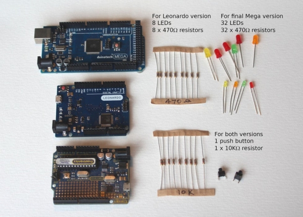
In this project we don’t use many different parts. However, we do use a lot of them. You will need:
- An Arduino.
All my examples will initially be built on Leonardo. You can also use a UNO, or pretty much any other Arduino with as many digital pins as you care to try connecting to LED’s. - LED’s – 8 will do.
The more the better (the code examples only use 8 LED’s) - 470 Ohm resistors (yellow, purple/violet, black, black and one other colour – usually gold).
You will need 1 for each LED you connect. So, for 8 LED’s, you need 8 470 Ohm resistors. - One push button switch SPST – momentary closed.
- One 10K resistor (brown, black, black, red and one other colour – usually gold).
- Medium to large Breadboard.
- Hookup wire.
If you want to make the final (Mega Blinky LED Extravaganze) project, you will need:
- An Arduino Mega
- 32 LED’s (or more if you are game). A mixture of colours is best.
- 32 of 470 Ohm resistors per LED (yellow, purple/violet, black, black and one other colour – usually gold).
NB: If you have more than 32 LED’s, you will need extra 470 ohm resistors. Basically, you need one 470 ohm resistor for each and every LED! - One push button switch SPST – momentary closed.
- One 10K resistor (brown, black, black, red and one other colour – usually gold).
- Large breadboard
- Hookup wire.
Step 3: Hook Everything Up
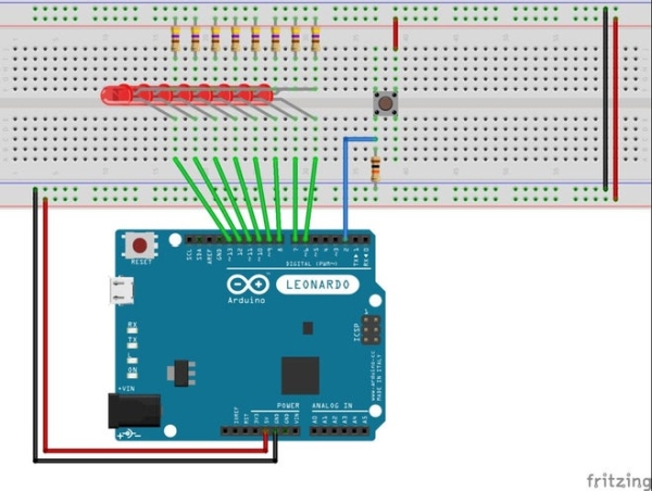
Hook up the components as shown in the diagrams. Unfortunately the breadboard view does not show the LED hookup very well, so I’ve also included the circuit diagram.
Fear not if you can not follow the diagrams, the connections are pretty straight forward:
- Power Connections
- Connect the 5V pin on Arduino to the two red rails on the breadboard (red wires)
- Connect the GND pin on Arduino to the two black (or blue) rails (Black wires).
- LED Connections
- Connect one end of the eight 470 ohm resistors to the 5V rail (no wire – just plug them in directly)
- Connect the other end of the eight 470 ohm resistors to the Anode (long wire) on each of the LED’s.
- Connect the other end of the eight LED’s to one of the Digital pins numbered 6 though 13 on the Arduino (Yellow wires).
- Push button Switch Connections
- Connect one pin of the switch to 5V (Red wire)
- Connect the diagonally opposite pin on the switch (refer to the breadboard diagram) to Pin 2 on the Arduino (Blue wire)
- Connect the 10K ohm resistor from the same pin to GND (again refer to the breadboard diagram).
That’s it. When running the programs below, if the LED’s do not light up, try checking their orientation:
- The Cathode (short lead) connects to one of the Arduino’s digital pins numbered 6 through 13.
- The Anode (long lead) connects to the 470 ohm resistor. The other end of the resistor connects to +5V.
If that is not the problem, double check all of the other connections.
Note about the examples
I’ve tried to provide plenty of examples to gradually illustrate the concepts.
I encourage you to try all of the examples, in sequence. However, if you are short of time, than please try at least these:
- Combined Chase and Blink.
- Interleaved LED Blink.
- Multitasking Chase and Blink.
- Object Oriented Chase and Blink.
Step 4: Blink an LED
In this simplest of examples, we will see how one task hogs the Arduino’s attention to the exclusion of everything else. This is non-cooperative behaviour which is also sometimes referred to as Single Threaded.
To see this uncooperative behaviour:
- Load the program below into your Arduino.
- Push the button. What does the LED do? It should eventually freeze in the off state when the button is pushed.
- Release the button. The LED should continue its rather monotonous blinking.
- Press the button while the LED is lit, then release it before 2 seconds passes (i.e. the delay time when it is turned off). What happens?
Nothing! it just keeps blinking (This will be better illustrated in the next example).
Why? Because the Blink task is hogging the CPU for a full 4 seconds. This prevents the Button press task to see that the button was pressed.
What we are seeing here is an example of a task occupying the Arduino’s CPU to the exclusivity of doing anything else. Specifically, when you press the button and this fact is eventually detected by the Arduino’s program (sketch), all other processing stops until such time as the button is released. This is not cooperative as each of the tasks (Blink and check button press) hog the CPU, without doing anything useful, until they have completed their individual operation.
Sure, we could change the algorithm in the checkButton function so that it does not wait until the button is released. We could replace the delay in the blink function with a loop and continuously poll the button, but that is not the point of this example. We will modify their behaviours, but not their function, when we start multitasking, without the need to add special polling code for looking for other activity throughout the program.
This way of programming is akin to the chef not being able to respond to the smoke alarm in the introduction. Programming the Arduino to continuously poll unrelated events is akin to asking the chef to continuously check for all possible disasters while chef is doing every other activity. This could make the programming very complex because if there were N activities and M possible “interrupts”, then the complexity of the code will be N x M. That is in each of the N activities, you will need to check for all possible M “interrupts” that might occur. Indeed, this style of programming is worse than the example we presented above. If we translated this example to the chef, it would be akin to the chef turning on the oven and sitting in front of it doing nothing else but waiting until the oven reached the target temperature. Only at that point in time, does chef start the next task – maybe filling the pot of water and sitting in front of it watching and waiting for it boil.
As we progress through the examples, hopefully you will come to realise that things can start to get complicated very quickly if we start changing basic operations and try to intermingle all of the function among each another. The fourth example – “Interleaved LED Blink” attempts to explicitly draw this complexity out.
Following is the code for example 1 – blink the LED
/******************************************************************************
 * Cooperative Multitasking
 *   01 - Blink LED
 *
 * This is the first in a series of programs to illustrate the benefits of
 * a simple multitasking mechanism for Arduino.
 *
 * This program (sketch) starts with the most basic non-cooperative multitasking example.
 * There are two subtasks:
 * - A "blink LED" task that blinks the LED. It will hold the CPU for the entire duration of a single
 *   LED blink operation.
 * -  A "check for button press" task. It will hold the CPU for as long as you hold the button down.
 *
 * When running this program we will note that:
 * a) The messages relating to the LED Blinking will continue to be displayed - even if the button is pressed
 *    until such time as the blink operation completes.
 * b) The messages relating to the LED Blinking and the blinking itself will cease being displayed if the
 *    button is pressed (once the "check button press" task gets a hold of the CPU).
 *
 * In short, neither routine is sharing the CPU (blinking stops during button press), even though the
 * "check button press" task isn't actually doing anything except waiting for the button to be released.
 * Similarly, the "Blink LED" task isn't doing anything useful once it turns the LED off or on. Indeed it
 * justs wastes CPU cycles courtesy of the "delay" function calls.
 *
 * In this simplistic example, we could code it differently to avoid much of the "system hanging" symptoms,
 * but that is not the purpose this example. The purposes of this example is to show how easily it is to
 * code a routine that is "blocking" other tasks from doing their thing.
 *
 * By the time we get to example 5, we will address this. Examples 2 and 3 build upon this example, but
 * still in a non-cooperative multi-tasking way.
 */// Define the pin for the input button
#define BUTTON_PIN 2
// define the LED PIN for blinking
#define LED_PIN       6void setup() {  Serial.begin (9600);
  while (!Serial)
  ;  Serial.println("Blinker will be on pin: ");
  Serial.println(LED_PIN);
  pinMode(LED_PIN, OUTPUT);
  digitalWrite(LED_PIN, HIGH);     // Turn the LED off.  // Set the push button's pin as an input.
  Serial.print("Setting input for push button on pin: ");
  Serial.println(BUTTON_PIN);
  pinMode(BUTTON_PIN, INPUT);

  Serial.println("Ready");
}/**********************
 * Check Button Pressed.
 * Checks to see if the button is pressed.
 * If it is, return true.
 *
 * The function will first check to see if the button is pressed, then wait for a bit to check
 * if the button is still pressed. If it is, then the button is "debounced" and this function
 * returns true (Button pressed).
 *
 * Otherwise this function returns false (Button not pressed).
 *
 * Return: true if button pressed, false otherwise.
 *
 */
boolean checkButtonPressed() {
  Serial.println("Check button press");
        // The complexity of this code is to "debounce" the button press.
        // Has the button been pressed.
  if (digitalRead(BUTTON_PIN) == HIGH) {
    // Check for a short period of time, that the button remains pressed.
    // In this case 50 x 1 ms checks.
    const int numChecks = 50;
    int i = 0;
    while (digitalRead(BUTTON_PIN) == HIGH && i < numChecks) {
      delay(1);
      i++;
    }
    // Did we exit the loop before the required time (i.e. was the button released / still being debounced)?
    if (i < numChecks) {
      return false;       // Return "Button not pressed"
    }    // At this point, we confirm that we have a button press.
    // Wait for the button to be released. During this time, whatever else was happening
    // on the Arduino (e.g. blinking an LED) will be suspended.
    Serial.println("Button pressed, waiting for release");
    while (digitalRead(BUTTON_PIN) == HIGH) {
      delay(10);
    }
    return true;          // Return "Button pressed"
  }
  return false;           // Return "Button not pressed"
}/**********************
 * Blink LED
 *
 * Blink the LED a single time.
 *
 */
void blinkLed() {
  Serial.println("LED On");
  digitalWrite(LED_PIN, LOW);
  delay(2000);  Serial.println("LED Off");
  digitalWrite(LED_PIN, HIGH);
  delay(2000);
}/**********************
 * Loop
 *
 * Continuously call the active routine (chase of blink LED).
 * Upon completion of the active routine, check to see if the button has been pressed.
 * If it has, print a message.
 */
void loop() {
  // Blink our LED for 2 seconds on, 2 seconds off.
  blinkLed();
  if(checkButtonPressed()) {
    Serial.println("Button was pressed (now it is released).");
  }
}
Step 5: LED Chaser
In this step, we will use a slightly more complicated example. The things to observe are similar as the Blink example, but we shall see more clearly how the pressing of the button is ignored until such time as the sequence completes.
Upload the program (sketch) below and the LED’s should light up one at a time giving a “chaser” type of effect.
- Observe the chaser pattern and push the button.
What happens? Nothing – until the sequence reaches the end at which time the chaser is frozen. The chase will remain frozen until such time as you release the button. - Release the button.
What happens? The chase resumes. - Press the button while the chaser is in motion and release it before the chaser completes its cycle.
What happens? Nothing! the chaser continues as though nothing has happened. This is because the “check button press” task never sees that the button is pressed.
Repeat the above, while monitoring the debug messages to get a different view on what is going on. Specifically, look at what happens at the “Check button press” message.
Here is the code for the Chaser:
/******************************************************************************
 * Cooperative Multitasking
 *   02 - LED Chasser
 *
 * This is the second in a series of programs to illustrate the benefits of
 * a simple multitasking mechanism for Arduino.
 *
 * This program (sketch) builds upon the blink programs by combining converting it into a chaser.
 * There are two subtasks:
 * - A "chase LED" task that causes each LED to light up one after the other. It will hold the CPU for
 *   the entire duration of a single chase operation. That is, individually light up the led's in one direction
 *   then the other.
 * -  A "check for button press" task. It will hold the CPU for as long as you hold the button down.
 *
 * When running this program we will note that:
 * a) The messages relating to the Chase operation will continue to be displayed - even if the button is pressed
 *    until such time as the chase operation completes.
 * b) The messages relating to the LED Chase and the chase itself will cease being displayed if the
 *    button is pressed (once the "check button press" task gets a hold of the CPU).
 *
 * In short, neither routine is sharing the CPU (chase stops during button press), even though the
 * "check button press" task isn't actually doing anything except waiting for the button to be released.
 * Similarly, the "Chase LED" task isn't doing anything useful once it turns the LED off or on. Indeed it
 * justs wastes CPU cycles courtesy of the "delay" function calls.
 *
 * In this simplistic example, we could code it differently to avoid much of the "system hanging" symptoms,
 * but that is not the purpose this example. The purposes of this example is to show how easily it is to
 * code a routine that is "blocking" other tasks from doing their thing.
 *
 * By the time we get to example 5, we will address this. Examples 2 and 3 build upon this example, but
 * still in a non-cooperative multi-tasking way.
 *
 */// Define the pin for the input button
#define BUTTON_PIN 2// Define the pins to be used in tracing mode.
unsigned int ledPins [] = {6, 7, 8, 9, 10, 11, 12, 13};void setup() {  Serial.begin (9600);
  while (!Serial)
  ;  // Initialise the LED Pins for output and set them to High (turn the LED's off).
  Serial.print("Initialising tracer pin: ");
  for (int i = 0; i < sizeof (ledPins) / sizeof(ledPins[0]); i++) {
    pinMode(ledPins[i], OUTPUT);
    digitalWrite(ledPins[i], HIGH);     // Turn the LED off.
    if (i > 0) {
      Serial.print(", ");
    }
      Serial.print(ledPins[i]);
  }
  Serial.println();

  // Set the push button's pin as an input.
  Serial.print("Setting input for push button on pin: ");
  Serial.println(BUTTON_PIN);
  pinMode(BUTTON_PIN, INPUT);

  Serial.println("Ready");
}/**********************
 * Check Button Pressed.
 * Checks to see if the button is pressed.
 * If it is, return true.
 *
 * The function will first check to see if the button is pressed, then wait for a bit to check
 * if the button is still pressed. If it is, then the button is "debounced" and this function
 * returns true (Button pressed).
 *
 * Otherwise this function returns false (Button not pressed)
 *
 * Return: true if button pressed, false otherwise.
 *
 */
boolean checkButtonPressed() {
  Serial.println("Check button press");
        // The complexity of this code is to "debounce" the button press.
        // Has the button been pressed.
  if (digitalRead(BUTTON_PIN) == HIGH) {
    // Check for a short period of time, that the button remains pressed.
    // In this case 50 x 1 ms checks.
    const int numChecks = 50;
    int i = 0;
    while (digitalRead(BUTTON_PIN) == HIGH && i < numChecks) {
      delay(1);
      i++;
    }
    // Did we exit the loop before the required time (i.e. was the button released / still being debounced)?
    if (i < numChecks) {
      return false;       // Return "Button not pressed"
    }
    // At this point, we confirm that we have a button press.
    // Wait for the button to be released. During this time, whatever else was happening
    // on the Arduino (e.g. blinking an LED) will be suspended.
    Serial.println("Button pressed, waiting for release");
    while (digitalRead(BUTTON_PIN) == HIGH) {
      delay(10);
    }
    return true;          // Return "Button pressed"
  }
  return false;           // Return "Button not pressed"
}/**********************
 * Tracer
 *
 * Cause the LED's to chase one another along the list of pins defined in "ledPins".
 * The chase will go from "left to right" as defined by the order of the pins in "ledPins". Then
 * "right to left".
 *
 * The chase will be executed one time.
 */
void tracer() {
  Serial.println("Tracer - up");
  for (int i = 1; i < sizeof (ledPins) / sizeof(ledPins[0]); i++) {
    digitalWrite(ledPins[i - 1], HIGH);   // Off
    digitalWrite(ledPins[i], LOW);        // On
//    Serial.print(ledPins[i]);
//    Serial.println(" On");
    delay(250);
  }

  Serial.println("Tracer - down");
  for (int i = sizeof (ledPins) / sizeof(ledPins[0]) - 2; i >= 0; i--) {
    digitalWrite(ledPins[i + 1], HIGH);   // Off
    digitalWrite(ledPins[i], LOW);        // On
//    Serial.print(ledPins[i]);
//    Serial.println(" On");
    delay(250);
  }
}/**********************
 * Loop
 *
 * Continuously call the active routine (chase of blink LED).
 * Upon completion of the active routine, check to see if the button has been pressed.
 * If it has, switch modes.
 */
void loop() {
  tracer();
  if (checkButtonPressed()) {
    Serial.println("Button was pressed (now it is released).");
  }
}
Step 6: Combined Chase and Blink
In this third example, I’ve combined the chase and the blink. The enhancement is that the button press will switch modes between chasing and blinking. We should see similar behaviour as before. Specifically:
- Pressing the button and releasing it before a cycle completes results in no change in behavior.
- Pressing and holding the button until a cycle completes will result in the LED freezing in the final state of its sequence until such time as you release the button.
Source: Cooperative Multitasking on Arduino – With Pretty Blinky Lights!