This project is an extension to the Speech Recognition with Arduino by leandro4b (http://www.instructables.com/id/Speech-Recognition…). However, instead of using 3 separate colored LEDs, I used a multicolor 4-channel RGBW LED Emitter. I had the opportunity of working at LED Engin last summer, which is why I was able to use the high power 4-die RGBW emitter ( LZ4-20MD00) for my project. You can purchase their RGBW emitter from Mouser here. I also got a lens that is paired with the emitter. This allows the colors to blend better, but it is optional for this project
The idea is simple: I want a voice activated LED program that allow me to change the color by modifying the amount of red, green, blue and/or white LED in the emitter. In addition to that, I wanted some preset functions where I can tell the light to “wake up”, “go sleep” or display the colors of the rainbow in order.
How this works: BitVoicer (voice recognition program) takes in a voice input, recognizes it and transfer that into a string. Every time it calls that particular string, the Arduino program will tell the LED what to do.
For this project, I used:
- BitVoicer – downloaded from http://www.bitsophia.com/BitVoicer.aspx
- Arduino UNO
- 10W RGBW LED Emitter
- data sheet here: http://www.ledengin.com/files/products/LZ4/LZ4-00M…
- Power Resistors
- one 4 Ohm 2W resistor (http://www.digikey.com/product-search/en?vendor=0&…)
- two 2.7 Ohm 2W resistors (http://www.digikey.com/product-detail/en/PR0200020…)
- one 2.4 Ohm 2W resister (http://www.digikey.com/product-detail/en/PR0200020…)
- Heat sink for the Emitter- created from Aluminum
- Lens (optional)
- Breadboard and wires
- USB Microphone
Step 1: Setting up LED Emitter and Heat Sink
When I got the emitter in the mail, It had no wires on them. The nice thing about the LZ4-20MD00 is that the LED is mounted on top of the MCPCB, which allows us to solder wires onto the LED more easily. There are 8 pads on the MCPCB- the data sheet tells me which pad is for which wire. I actually had some challenges while soldering the wires onto the MCPCB because the MCPCB sucks the heat away, making it difficult for the soldering iron to heat up the pads. I then realized that the data sheet actually had tips for soldering. For this particular emitter from LED Engin, I had to heat the emitter up with a hot plate to 125-150 degrees C before soldering the wires on. Caution: different manufacturers have different procedures for attaching the wires- make sure you don’t overheat the emitter.
According to the data sheet (on pg. 7 and 15), these are the wires connected to each pad:
Pad 1: White Anode +
Pad 8: White Cathode –
Pad 7: Red Anode +
Pad 6: Red Cathode –
Pad 5: Green Anode +
Pad 4: Green Cathode –
Pad 3: Blue Anode +
Pad 2: Blue Cathode –
I suggest that you use colored tape to indicate which wire is for which color so that you don’t get confused later on.
Since this is a high power LED, I needed a heat sink for the emitter so that the LED does not overheat.
I made a simple heat sink out of aluminum and attached it to the LED Emitter using screws.
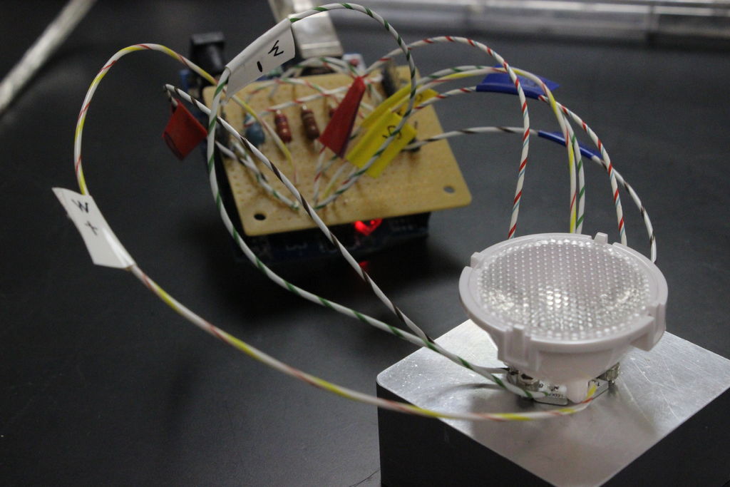
Step 2: Hardware
Wire the the Arduino and LEDs according to the diagram above.
Depending on which 4-channel LED you get, you will need to get different power resistors for each channel.
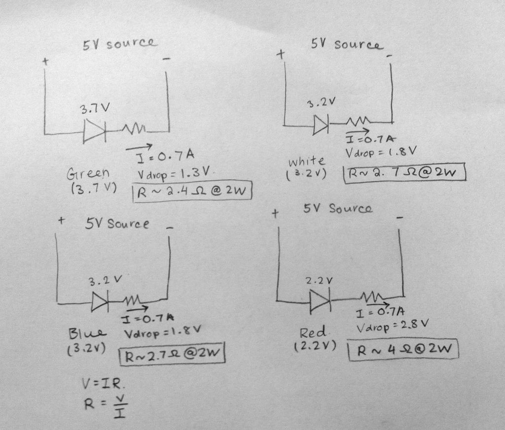
For my RGBW 4-channel emitter, I looked for the Electrical Characteristics on pg. 5 of the data sheet, then determined the power resisters I wanted using the information. I looked for the forward voltage and the typical voltage drop across each LED, then I used ohms law to determine the resistor that should go with each color. Note that you should use 2W power resistors because these are high power LEDs.
For this LED Emitter, I am using:
- 4 Ohm 2W power resistor for red channel
- 2.7 Ohm 2W power resistor for white channel
- 2.7 Ohm 2W power resistor for blue channel
- 2.5 Ohm 2W power resistor for green channel
I am also powering the LED using the 5V source from the Arduino.
Step 3: Upload Codes and Files
After downloading BitVoicer and Arduino, I wrote some codes for Arduino and created a new file for BitVoicer. I have included both files in the attachment of this instructable. (Note: you will not be able to open the vsc file unless you have BitVoicer installed). To start the program, first upload the Arduino code, and then press the start button in the BitVoicer file.
LED is not responding to your voice? Check these things under Preferences (under File) for BitVoicer:
- Bits per Second is set to: 115200
- Audio input is Computer’s Default Microphone
- set the Port Name to the same port that is connected to the Arduino (named COM_)
If still doesn’t work, try these things under Preferences (under File) for BitVoicer:
- lower the Acceptable Confidence level
- make sure the Computer’s Default Microphone is set to your external USB microphone. Look for the microphone setting on your computer.
For more detail: Voice Activated LED Lighting with Arduino