Summary of Virtual Etch A Sketch
This article describes a DIY virtual Etch A Sketch project using an Arduino, potentiometers, and an optional accelerometer. The author explains how to connect hardware components to simulate the classic drawing toy's analog feel, including shaking to clear the screen. The guide covers installing necessary libraries for Arduino and Processing, calibrating sensor values, and running the final code to create an interactive digital drawing experience in about one hour.
Parts used in the Virtual Etch A Sketch:
- 1 x Arduino
- 2 x Potentiometers
- 1 x Accelerometer
- 1 x Breadboard
- 2 x Small pieces of material (approx 5x5 inches)
- 4 x Standoffs
- Lengths of wire
The Etch A Sketch: famous, creative, and unique. Unfortunately I have no clue where the one from my childhood is, so I decided to make my own virtual one! Check it out (and my awful drawing skills) below.
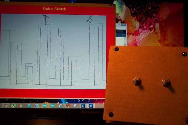
This Etch A Sketch is quite like the original, (while it will never replace it, it’s still lots of fun) as the analog noise makes the lines a bit squigly like the real thing. The shake to clear is also very entertaining, which only leaves you to make the pleasant “shhk shhk” noise of the sand to complete the experience (definitely necessary, but maybe do this quietly in public to avoid the stares). It’s like an Etch A Sketch video game.
This is a fun and simple project (took me 3 hours to write the code, test, and build, so if you have the parts should be ~1 hour) and is a good introduction into potentiometers, accelerometers, arduino, and processing. Anyways, have fun!
Step 1: Parts List
Fortunately, the parts required for this project are simple and cheap. You might even have them all!
Parts:
1 x arduino (any kind of course)
2 x potentiometers (resistance value doesn’t matter, mine are 10k ohm)
1 x accelerometer (this is optional, but adds some fun. Mine is only one degree so any will work)
1 x breadboard (not necessarily needed, just makes things easier)
2 x small piece of material approx 5 in by 5 in (wood, cardboard, whatever)
4 x some sort of standoffs for mounting the two pieces of material together
Some lengths of wire to breadboard.
Random tools will also be needed to mount and screw whatever material you’re using together.
Step 2: Potentiometers
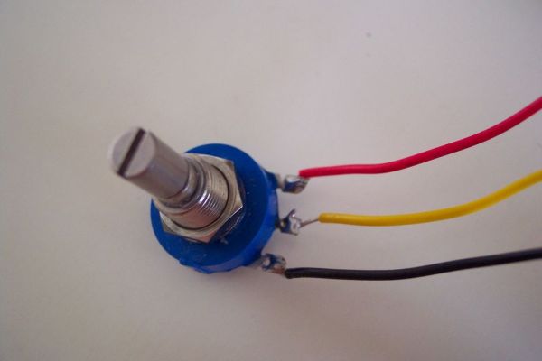
Now to learn about potentiometers (or pots)! They are in fact variable resistors and we will be using the Arduino to read the resistance value from it to determine where the program should draw the lines.The majority of them will have three leads for you to attach wires too, as seen in the first picture. In order from left to right we have the ground wire, the signal wire (goes to an analog port), and the power line (5v).
In order to make them useful, you will need to run a simple test program on the Arduino to find the min (most likely 0) and max values that the potentiometer will have when you call analogRead(pin); I have a sample sketch of this HERE. Just download the “TestPotentiometer” file and run it in arduino. Make sure you have the potentiometer in the first analog port (A0). Record these max and min values as you will have to enter them in the processing program for accurate readings!
Step 3: Accelerometer
Next we have the accelerometer. Really any one will do, but they are not totally necessary! It’s just really fun to shake it and have it clear. These hook up to the arduino in the same way as the pots (ground, 5v, and analog signal wire) the wires should be color coded so you know which is which. Similar to the potentiometer test, you also need to find the max accelerometer value. You can actually do this with the potentiometer test code, just make sure you pick the right analog port. Record the maximum value (minimum doesn’t matter).
Step 4: Arduino
For this project we need the Arduino (If you’ve never used it before, it can be downloaded HERE) to communicate with processing. Fortunately for both of us some smart people have already developed an Arduino library to do just that! The Arduino IDE already has the example in it so all you need to do is click File then go to Examples. Scroll down to Firmata and select Standard Firmata, the program will open. Make sure your Arduino is connected to the computer and upload it.
Step 5: Processing
Now for the Arduino to talk to Processing (Processing can be downloaded HERE) you will need a new Processing library (don’t worry you just download one file and move it into the Processing libraries) the people on Arduino’s site have the library for download and an easy step by step of how to move it to the correct location! The link to that page is right HERE.
Next you will need my processing sketch which is available HERE. Once you have my sketch open, click the run button and if the Etch A Sketch frame pops up you are good to go! If not, check to make sure you correctly loaded the Arduino program and Processing library.
To ensure beautiful drawings, insert the max and min values you found for the potentiometers’ into the 5th line of code where it says
“int min1 = 0, min2 = 0, max1 = 1023, max2 = 1023;”
For the accelerometer put your max vallue into the line that reads “int MAX_ACCEL = 624;”
For more detail: Virtual Etch A Sketch
- What parts are required for this project?
You need an Arduino, two potentiometers, an optional accelerometer, a breadboard, two small material pieces, four standoffs, and wires. - How do you connect the potentiometers to the Arduino?
Connect the ground wire, signal wire to an analog port, and power line to 5v from left to right. - Can you use any type of accelerometer?
Yes, any accelerometer will work, though it is optional but adds fun by allowing you to shake the device to clear the screen. - Does the resistance value of the potentiometers matter?
No, the resistance value does not matter; the author used 10k ohm pots. - How do you calibrate the potentiometer readings?
Run a test program on the Arduino to find the min and max values when calling analogRead and record them for the Processing code. - Which library must be uploaded to the Arduino IDE?
You must upload the Standard Firmata example found under File then Examples in the Arduino IDE. - How do you ensure accurate drawings in Processing?
Insert the recorded max and min values for the potentiometers into the specific lines of code in the Processing sketch. - What creates the squiggly lines in the virtual version?
The analog noise makes the lines squiggle like the real thing.