Summary of Traffic Signal / Stop Light Wiring with Arduino Controller
Summary: This article explains how to convert an old traffic signal into a functioning Arduino-controlled traffic light. It provides wiring guidance, required components, Arduino code that cycles normal, blinking-red, and blinking-yellow modes, and practical notes on connectors, power supplies, and tools. The author used an Arduino Uno, a 4-channel relay module, and household power wiring to drive the signal.
Parts used in the Traffic Signal with Arduino Controller:
- Old traffic signal (plastic or metal housing)
- Arduino Uno
- SainSmart 4-Channel 5V Relay Module
- Power supply / wall wart (7V to 12V, example 12V 750mA)
- Male-to-female jumper wires (or male-to-male + Molex connector as used)
- Lamp or appliance cord with ground wire
- 16 gauge wire (for internal line voltage wiring)
- Solder and soldering iron
- Sheet metal screws
- Wire nuts
- Epoxy (to secure transformer)
- Heat shrink tubing
- USB B cable (to program Arduino)
- Wire cutters and wire strippers
- Mini flat head screwdriver (for relay connections)
- Cordless drill
- Dremel tool with milling bit
- Eye and hearing protection
I always wanted an old traffic signal and finally got one recently. However, it was very simply wired so that all the lights were fixed on. What fun is that? I also wanted to try out an Arduino controller and thought this would be a nice simple project to incorporate it into.
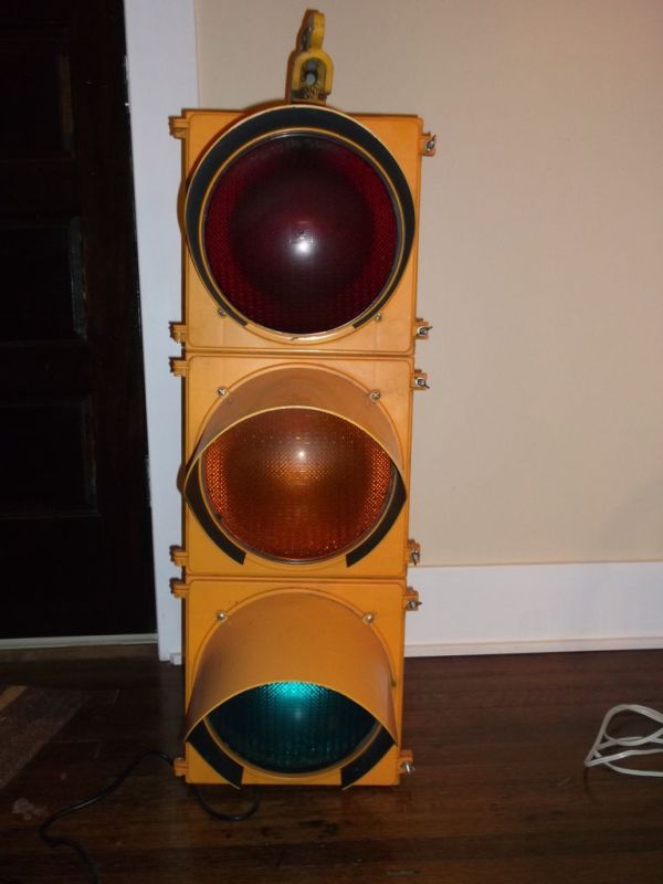
This Instructable will show you how to wire up an old traffic signal with an Arduino controller to function like a real traffic light. I used a pretty simple program and controls. Given the power of the Arduino controller, there are a lot of ways you can customize this.
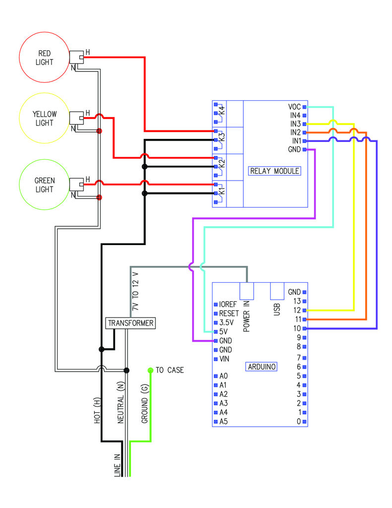
Step 2: The plan
Below is a wiring diagram for the traffic signal. Hopefully this is pretty clear what gets wired to what.
Above is a photo of the Arduino Uno and the relay module with the wiring between the two attached. I only had male to male jumpers, so I used a Molex connector and my mad soldering skills to make a connector (second photo). It is probably easier to use male to female jumpers to connect everything or find a 6 pin jumper to use. The Arduino has all female sockets and the relay module has all male pins.
If you have not used an Arduino before, see this Instructable by randofo: http://www.instructables.com/id/Intro-to-Arduino/
Download and start the Arduino programming software if you have not already. Connect the Arduino to your computer with a USB B cable.
Copy and paste the code the below and upload it to the Arduino. One the code uploads it should start running immediately on the Arduino. You should see the indicator lights going on and off on the relay unit and hear the relay switches tripping.
You can make this more simple or complicated if you want. I have it set up to cycle through 25 normal cycles, switch to blinking red for a few minutes, do 25 more normal cycles, switch to blinking yellow for a few minutes, and then repeat.
//Fzumrk’s traffic controller code
// name your pins:
int red = 12;
int yellow = 11;
int green = 10;
// the setup routine runs once when you press reset:
void setup() {
// initialize the digital pin as an output.
pinMode(red, OUTPUT);
pinMode(yellow, OUTPUT);
pinMode(green, OUTPUT);
}
int var = 0; //defines and sets initial value for variables used below
int var1 = 0; //defines and sets initial value for variables used below
// the loop routine runs over and over again forever:
void loop() {
// sets initial value for pins so that lights start as “off”
digitalWrite(green, HIGH);
digitalWrite(yellow, HIGH);
digitalWrite(red, HIGH);
while(var < 25){
// repeats normal cycle 25 times
digitalWrite(green, LOW); // turns the green light on
delay(20000); // holds the green light on for 20 seconds
digitalWrite(green, HIGH); // turns the green light off
delay(600); // slight pause between lights
digitalWrite(yellow, LOW); //turns the yellow light on
delay(4000); //holds the yellow light for 4 seconds (watch out for that red-light camera!)
digitalWrite(yellow, HIGH); //turns the yellow light off
delay(600); //slight pause between lights
digitalWrite(red, LOW); //turns the red light on
delay(20000); //holds the red light on for 20 seconds
digitalWrite(red, HIGH); //turns the red light off
delay(600); //slight pause between lights
var++;} //adds 1 to variable “var” for repeat count
// after 25 cycles above, the light switches to “power outage mode”, flashing red
delay(600); //slight delay
var1=0; //resets variable “var1” to 0
while(var1 < 120) {
// repeats power outage cycle 120 times – 2 minutes
digitalWrite(red, LOW);
delay(600);
digitalWrite(red, HIGH);
delay(400);
var1++;}
var = 0;
//switches back to normal cycle after “power outage” cycle is done
while(var < 25){
// back to normal light cycle for 25 cycles
digitalWrite(green, LOW); // turn the LED on (HIGH is the voltage level)
delay(20000); // wait for a second
digitalWrite(green, HIGH); // turn the LED off by making the voltage LOW
delay(600); // wait for a second
digitalWrite(yellow, LOW);
delay(4000);
digitalWrite(yellow, HIGH);
delay(600);
digitalWrite(red, LOW);
delay(20000);
digitalWrite(red, HIGH);
delay(600);
var++;}
delay(600);
//switches to “late night cycle” flashing yellow for 2 minutes, similar to flashing red above
var1=0;
while(var1 < 120) {
digitalWrite(yellow, LOW);
delay(600);
digitalWrite(yellow, HIGH);
delay(400);
var1++;}
var = 0;
//goes back to normal cycle at top and repeats forever
}
The brains of this thing are going to be an Arduino Uno connected to a relay module.
Arduino Uno
http://www.amazon.com/Arduino-UNO-board-DIP-ATmega328P/dp/B006H06TVG/ref=sr_1_1?ie=UTF8&qid=1362360128&sr=8-1&keywords=arduino+uno
SainSmart 4-Channel 5V Relay Module
(Note: This relay is pretty loud. I can hear it click from across the room. If anyone has suggestions for something similar that is not as noisy, let me know.)
You will need a power supply (transformer, wall wart, AC/DC adapter) for the Arduino. I used a 12V 750mA wall wart that I had from some other piece of electronics that had died. Most 7V to 12 V transformers should work. You can pick one up at Goodwill for about $2. Stay away from Radio Shack, they wanted $20-$30 for wall warts! I am sure someone who knows more about the Arduinos can chime in as to what kind of amperage range you should stay in. Here’s one from Amazon that should work fine:
You will also need some male to female jumpers to connect the Arduino to the relay module (note, I did not have these but wish I did):
http://www.amazon.com/Jumper-Wires-Premium-200mm–Female/dp/B008MRZSH8/ref=sr_1_1?s=electronics&ie=UTF8&qid=1362360630&sr=1-1&keywords=jumper+wire+male+to+female
Note: If you do not want to mess with the Arduino, there are a couple ready to go traffic signal controllers available online. I could have gone this route, but I was really wanting to try out the Arduino:
http://www.ecrater.com/p/12018399/micro-3-traffic-light-signal-controller
http://trafficlightwizard.com/3colorsequencerkitforrotationofflashinglight.aspx
A lamp or appliance cord with ground wire
Other materials you will need will depend on the starting state of your traffic signal. I used some 16 ga wire (for the internal line voltage wiring), solder, sheet metal screws (for securing the Arduino and relay module, and attaching ground wires to the frame), wire nuts (for connecting line voltage wires), epoxy (to secure transformer), heat shrink tubing (to insulate transformer connections).
Tools:
You will need a USB B cable to connect the Arduino to your computer to program it. If you have a USB printer you should already have one of these.
Wire cutters
Wire strippers
mini flat head screwdriver for relay connections
Other tools you will need will again depend on the initial state of your traffic signal. I used the following:
Cordless drill (for drilling holes in the case)
Soldering Iron (for wire connections and heat shrink tubing)
Dremel tool with milling bit (cut off some the plastic in the case to make mounting the new components easier)
Eye and hearing protection if you are using power tools.
Software:
You will need the Arduino programming software to upload the code to the Arduino:
http://arduino.cc/en/main/software
For more detail: Traffic Signal Wiring with Arduino Controller
- What Arduino pins are used for the red, yellow, and green lights?
The code names red as pin 12, yellow as pin 11, and green as pin 10. - How long does the green and red stay on during the normal cycle?
Both green and red are held on for 20 seconds each in the normal cycle. - How long is the yellow light during the normal cycle?
The yellow light is held on for 4 seconds during the normal cycle. - How many normal cycles run before switching to blinking red?
The program cycles through 25 normal cycles before switching to blinking red. - How long does the blinking red power outage mode run?
The blinking red mode repeats 120 times, which the author describes as 2 minutes. - What components form the brains of the traffic signal controller?
The brains are an Arduino Uno connected to a 4-channel 5V relay module. - Can you use a different ready-made controller instead of Arduino?
Yes, the article notes there are ready-to-go traffic signal controllers available online as an alternative. - What connector issue did the author encounter between Arduino and relay module?
The Arduino has female sockets and the relay module has male pins; the author lacked male-to-female jumpers and used a Molex soldered connector instead. - What power supply voltages are suggested for the Arduino?
Most 7V to 12V transformers should work; the author used a 12V 750mA wall wart. - What audible characteristic does the chosen relay module have?
The SainSmart 4-channel relay module is described as pretty loud and you can hear it click from across the room.